Non-electrically conductive thermal dissipator for electronic components

a technology of non-electrical conductive and thermal dissipation device, which is applied in the direction of cooling/ventilation/heating modification, semiconductor/solid-state device details, televisions, etc., can solve the problems of increasing complexity of circuit designs of modern electronic devices such as televisions, radios, and communications equipment, and the size of devices has continued to shrink

Inactive Publication Date: 2004-03-16
PARKER INTANGIBLES LLC
View PDF37 Cites 82 Cited by
  • Summary
  • Abstract
  • Description
  • Claims
  • Application Information

AI Technical Summary

Benefits of technology

FIG. 1 is a perspective view of a low profile, generally planar thermal dissipator which, in accordance with the present invention, includes an electrically non-conductive ceramic thermal dissipati

Problems solved by technology

Circuit designs for modern electronic devices such as televisions, radios, computers, medical instruments, business machines, communications equipment, and the like have become increasingly complex.
Although the complexity of the designs has increased, the size of the devices has continued to shrink with improvements in the ability to manufacture smaller electronic components and to pack more of these components in an ever smaller area.
As electronic components such as IC semiconductor chips or dies have become smaller and, in turn, more densely packed on printed circuit boards (PCBs), designers and manufacturers now are faced with the challenge of how to dissipate the heat which is ohmicly or otherwise generated by these components.
Indeed, it is well known that many electronic components, and especially power semiconductor components such as transistors and microprocessors, are more prone to failure or malfunction at high temperatures.
Thus, the ability to dissipate heat often is a limiting factor on the performance of the component.
However, these plastic materials generally exhibi

Method used


Image

  • Non-electrically conductive thermal dissipator for electronic components
  • Non-electrically conductive thermal dissipator for electronic components
  • Non-electrically conductive thermal dissipator for electronic components

Examples


Embodiment Construction

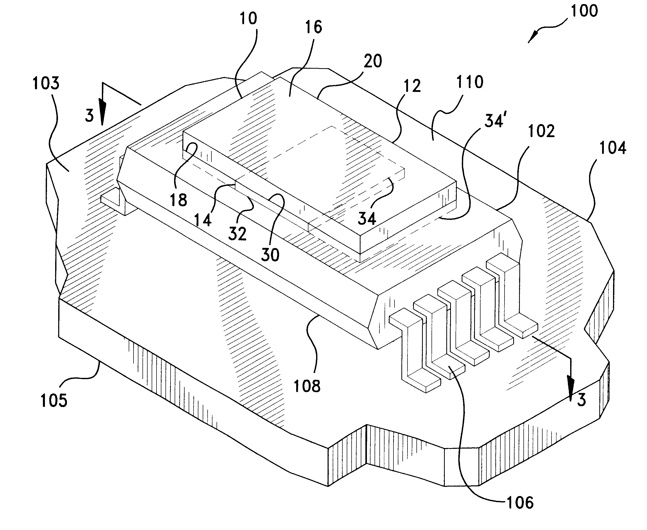
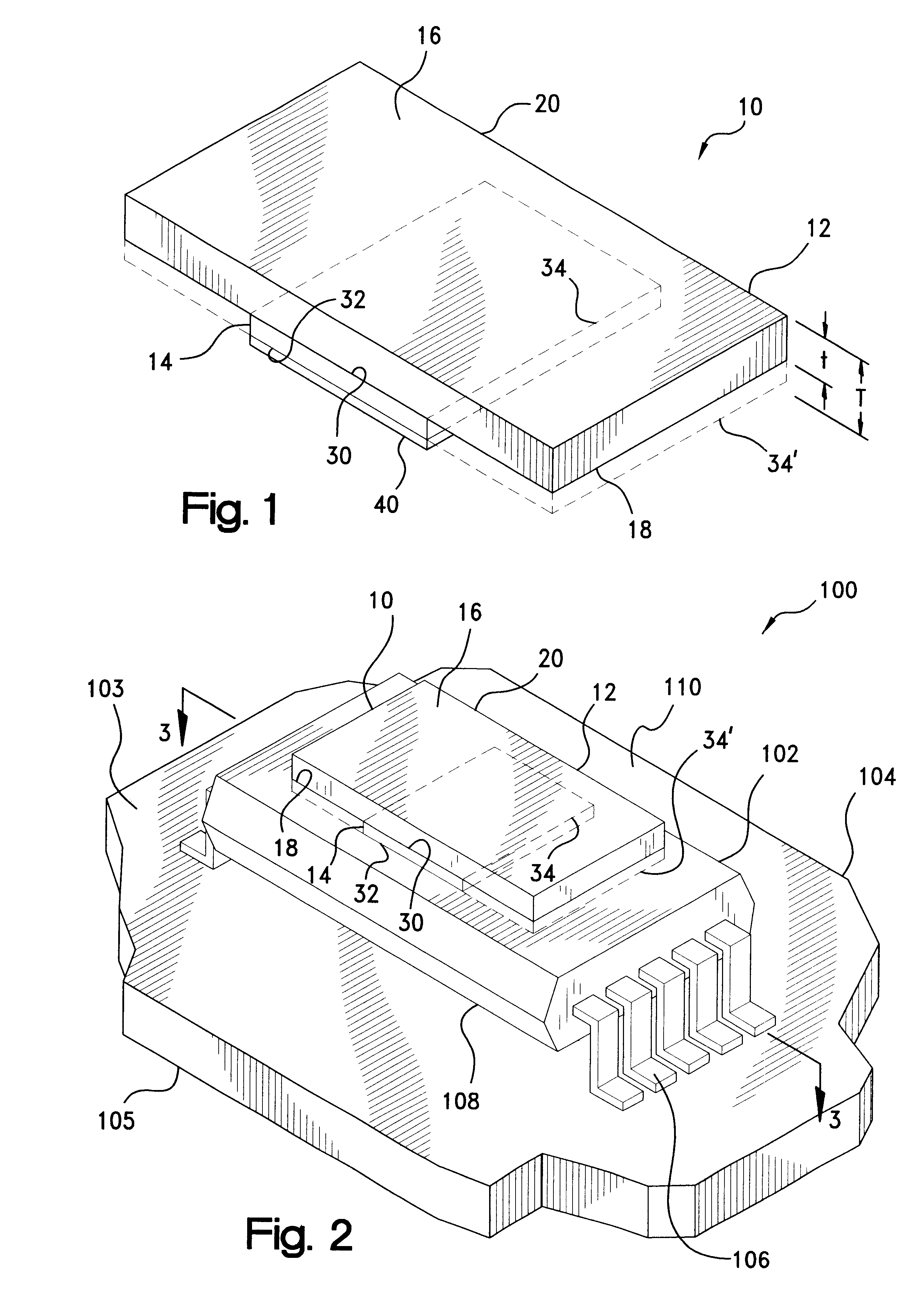
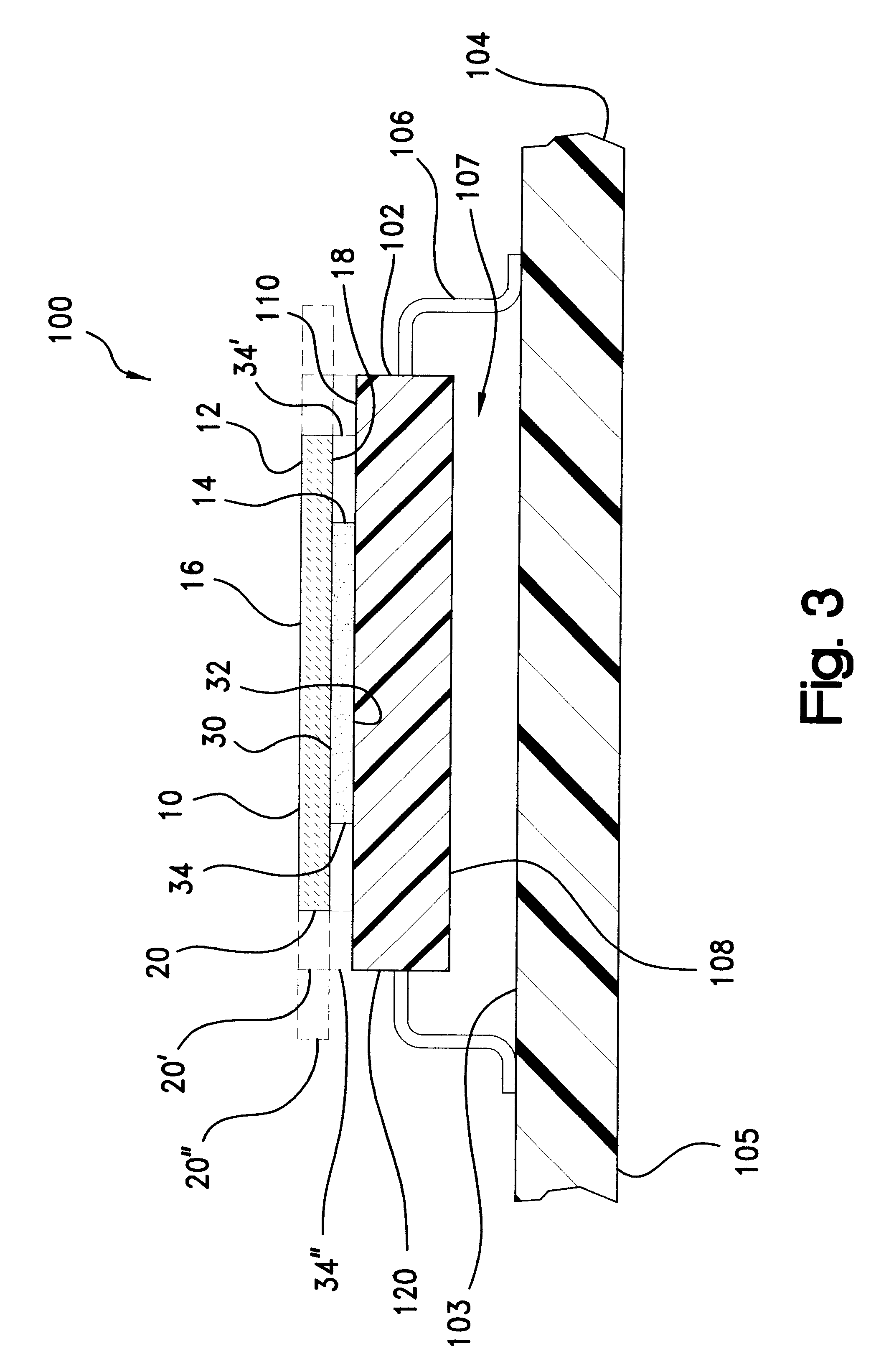
Representative thermal dissipators according to the present invention were constructed for characterization. Samples were prepared by laser cutting a 60 mil sheet of alumina (96% Alumina, Coors Ceramic Co., Golden, Colo.) into a 1.8-inch by 1.8-inch square, and by laser cutting a 50 mil sheet of aluminum nitride (Accumet Engineering Corp., Hudson, Mass.) into a 1.25-inch by 1.25-inch square. Onto one side of each of the ceramic squares was applied a 3 mil thick layer of a silicone pressure sensitive adhesive (Thermattach.TM. T410, Parker Chomercis Division, Hudson, N.H.).

Each of the samples so prepared were surface mounted under an application pressure of less than 3 psi to an AMD Am386SLX-25, 100 lead PQFP microprocessor die coupled to a 2 watt external power supply. The Vcc and GND leads of the PQFP were soldered to an Analysis Tech PGA100T FR-4 test board in accordance with EIA and JEDEC recommendations.

The test apparatus was calibrated in a temperature controlled, dielectric flu...


PUM


Abstract

A thermal dissipator disposable in a heat transfer relationship with a heat-generating source, such as an electronic component, which is mounted on a substrate, such as a printed circuit board. The dissipator includes a thermal dissipation member having a top and bottom surface, and a pressure sensitive adhesive layer disposed on the thermal dissipation member to cover at-least a portion of the bottom surface thereof. The dissipation member is formed of a thermally-conductive, electrically-nonconductive ceramic material. The pressure sensitive adhesive layer has an inner surface adhered to the bottom surface of the thermal dissipation member, and an outer surface bondable to a heat transfer surface of the source for attaching the dissipator to the source in a heat transfer relationship therewith.

Description

The present invention relates broadly to thermal management devices for electronic components, such as integrated circuit (IC) chips. More particularly, the invention relates to a non-electrically conductive, low profile thermal dissipator for attachment to the heat transfer surface of an electronic component for the conductive and / or convective cooling of the component.Circuit designs for modern electronic devices such as televisions, radios, computers, medical instruments, business machines, communications equipment, and the like have become increasingly complex. For example, integrated circuits have been manufactured for these and other devices which contain the equivalent of hundreds of thousands of transistors. Although the complexity of the designs has increased, the size of the devices has continued to shrink with improvements in the ability to manufacture smaller electronic components and to pack more of these components in an ever smaller area.As electronic components such ...

Claims


Application Information

Patent Timeline
IPC IPC(8): H01L23/373H01L23/34
CPCH01L23/3731H01L23/3735H01L2924/3011Y10S165/905H01L2924/0002H01L2924/00
Inventor SORGO, MIKSA DE
Owner PARKER INTANGIBLES LLC
Why Eureka
Try Eureka