Method for the removal of adsorbed molecules from a chamber

a technology of adsorbed molecules and chambers, which is applied in the direction of cleaning hollow objects, lighting and heating apparatus, and using liquids to clean, etc. it can solve the problems of adversely affecting the process, adversely affecting the formation of oxygen-free surface layers, and adversely affecting the so-called cop's or crystal originated particles, so as to accelerate the desorption of undesired first molecules, prevent a renewed adsorption, and increase the throughput rate of the uni

Inactive Publication Date: 2004-12-14
MATTSON TECHNOLOGY +1
View PDF7 Cites 8 Cited by
  • Summary
  • Abstract
  • Description
  • Claims
  • Application Information

AI Technical Summary

Benefits of technology

Pursuant to the present invention, the object is realized by introducing second polar molecules into the chamber that exert a desorptive effect upon the first molecules. The introduction of the second polar molecules accelerates the desorption of the undesired first molecules. After detaching the first molecules, the second polar molecules preferably assume the location of the first molecules, thus preventing a renewed adsorption. As a consequence, more rapidly prescribed threshold values can be achieved for the concentration of the first molecules within the chamber, as a result of which the throughput rates of the unit, and hence its economy, can be increased. At the same time, lower values of the concentration of the first molecules can be achieved within the chamber, which leads to improved process results. The first molecules are preferably water and/or oxygen molecules that can have an etching effect upon the semiconductor wafer. By removing these molecules, damage to the wafers or the structures provided thereon can therefore...

Problems solved by technology

With many methods carried out within a processing chamber, such as, for example, CVD processes or thermal treatments of objects, especially in the semiconductor industry and microelectronics, moisture can, for example, adversely affect the process.
In addition, water adversely affects so-called COP's or crystal originated particles, as well as the formation of oxygen-free surface layers (magic denuded zones).
The water molecules adsorbed on the chamber walls or on the substrates lead to undesired chemical reactions that adversely affect a treatment result.
Structures provided on the substrate surface can ...

Method used


Image

  • Method for the removal of adsorbed molecules from a chamber
  • Method for the removal of adsorbed molecules from a chamber
  • Method for the removal of adsorbed molecules from a chamber

Examples


Embodiment Construction

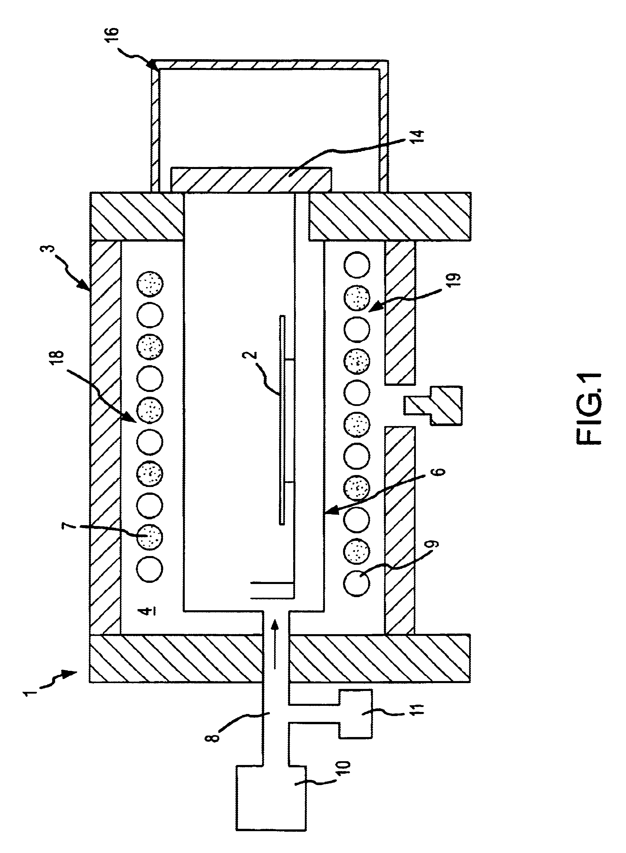
FIG. 1 shows a schematic illustration of a rapid heating unit 1 for the thermal treatment of substrates 2, as known, for example, from the not-prepublished DE 199 23 400.0 of this same applicant. The apparatus 1 has a housing 3, which in the interior can include a reflective chamber 4. Provided within the housing 3 is a processing chamber 6 that is made, for example, of quartz. Within the processing chamber 6 a support is provided for accommodating and holding a semiconductor wafer 2. The processing chamber 6 is provided at one end with a gas inlet line 8 that is in communication with at least two different sources of gas 10 and 11. An end of the processing chamber 6 opposite the gas line 8 is closed off by a chamber door 14. In the region of the chamber door 14, a transfer chamber 16 can be provided on the outer side of the housing 3 via which, in a known manner, semiconductor wafers 2 are introduced into the processing chamber 6 and are removed therefrom.

The processing chamber 6 i...


PUM

PropertyMeasurementUnit
Angleaaaaaaaaaa
Temperatureaaaaaaaaaa
Pressureaaaaaaaaaa

Abstract

A method of removing first molecules adsorbed on the surfaces of a chamber and/or at least one object found in the chamber is provided. Second, polar molecules that have a desorptive effect on the first molecules are introduced into the chamber. The second molecules comprise nitrogen and hydrogen, and especially NH3 molecules.

Description

The present invention relates to a method for the removal of first molecules that are adsorbed upon the surfaces of a chamber and / or of at least one object located in the chamber, in particular to the removal of polar molecules from a processing or transfer chamber of a rapid heating unit.With many methods carried out within a processing chamber, such as, for example, CVD processes or thermal treatments of objects, especially in the semiconductor industry and microelectronics, moisture can, for example, adversely affect the process. Moisture tends to become adsorbed on the chamber walls, the objects, such as, for example, semiconductor substrates, or other elements in the chamber. Examples of processes that are adversely affected by the presence of water are the production of ultra shallow pn-junctions (ultra shallow junctions), metalizing or coating processes, and many CVD processes. In addition, water adversely affects so-called COP's or crystal originated particles, as well as th...

Claims


Application Information

Patent Timeline
IPC IPC(8): C23C14/56H01L21/00C23C16/44H01L21/205H01L21/324
CPCC23C14/564C23C16/4408H01L21/67098Y10S438/905Y10S134/902Y10S438/906C23C14/56
Inventor NENYEI, ZSOLTLERCH, WILFRIEDNIESS, JURGENGRAF, THOMAS
Owner MATTSON TECHNOLOGY
Why Eureka
Try Eureka