
Fluid driven agitator used in densified gas cleaning system

a technology of densified gas and agitator, which is applied in the direction of rotary stirring mixer, cleaning using liquids, transportation and packaging, etc., can solve the problems of conventional solvents, toxic contaminants and detergents are dissolved in water, and subsequent drying steps, etc., and achieve cost and difficulty in downsizing, short life-span

Inactive Publication Date: 2005-01-04
METAL INDS RES & DEV CENT
View PDF19 Cites 61 Cited by
  • Summary
  • Abstract
  • Description
  • Claims
  • Application Information

AI Technical Summary

Benefits of technology

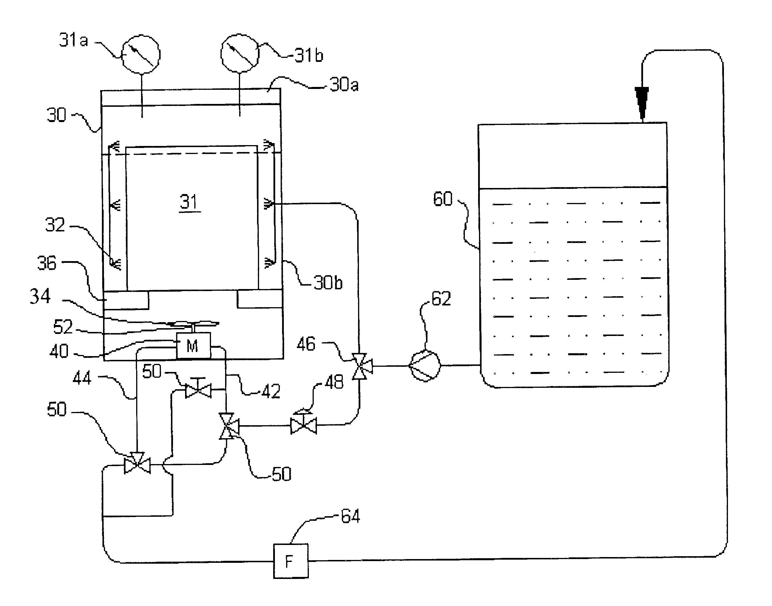
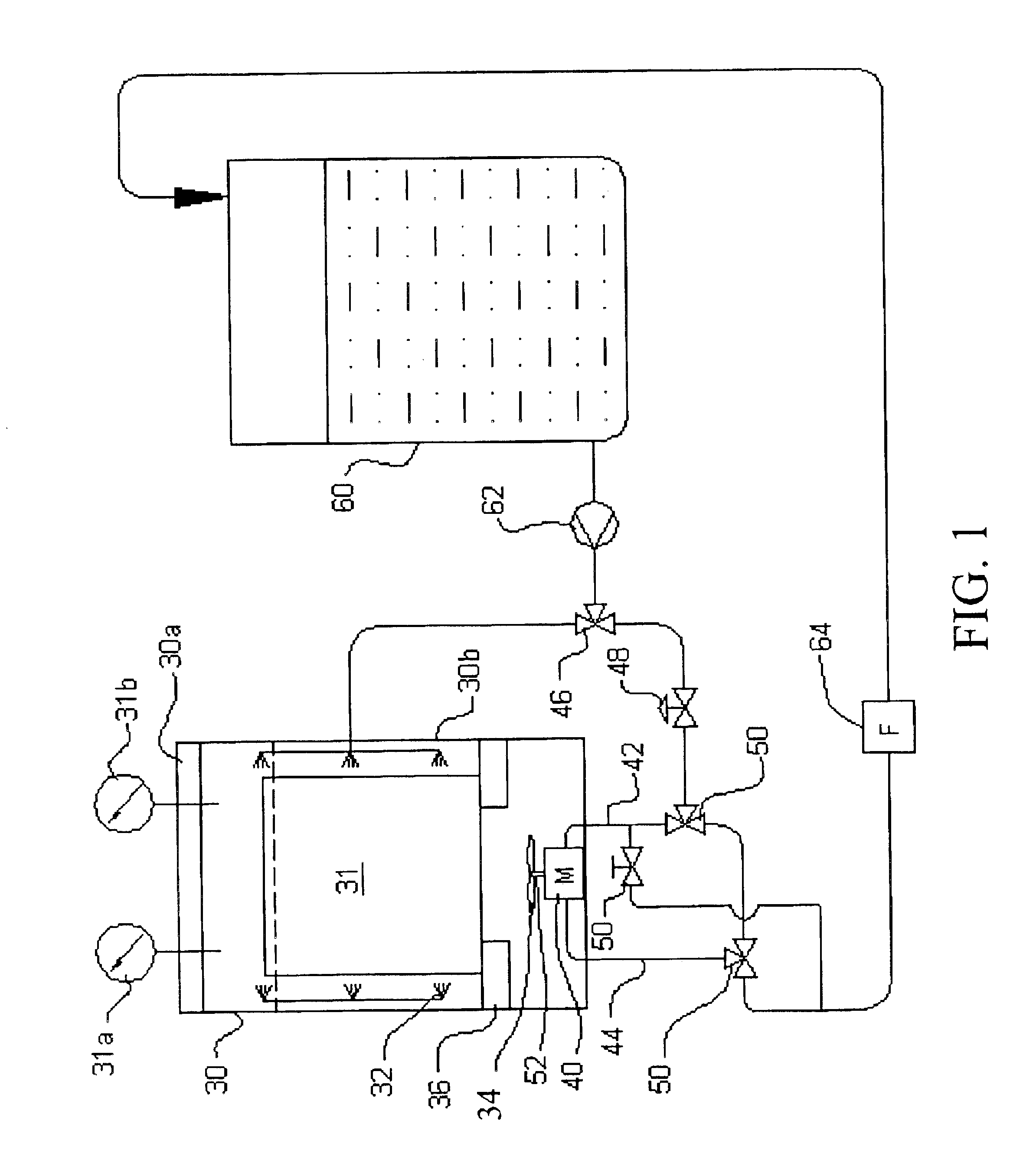
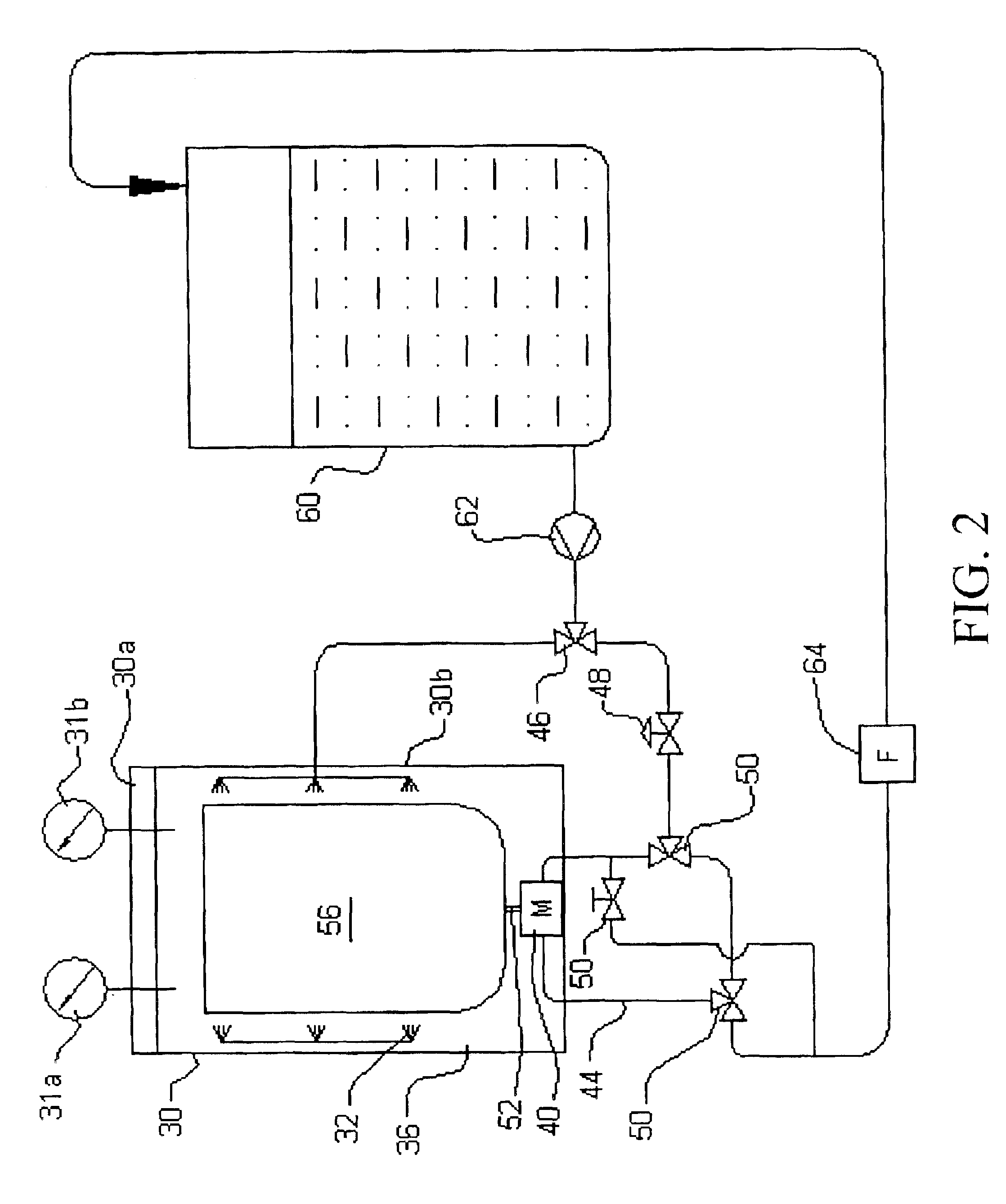
The invention provides a fluid driven agitator for a densified gas cleaning system that overcomes problems of complicated structure, short life-span, and difficulty in downsizing for conventional agitators. The agitator uses a hydraulic motor mounted in a cleaning vessel, which serves as a hydraulic source. The system provides fully leakage-free and advantages of simple structure, small size, and low cost. The agitator can be used with a rotary basket or a rotary rod for cleaning delicate articles. The invention solves the problem of complicated structure, short life-span, and difficulty in downsizing for conventional agitators.

Problems solved by technology

However, such wet cleaning types requires a subsequent drying step.
Besides, toxic contaminants and detergents are dissolved in water or solvents, which need to be treated before drainage.
Nowadays, the gradually stringent provisions for environmental protection progressively ban the use of conventional solvents due to the air pollution, ozone depletion, and greenhouse effect resulted from the use of such solvents.
Moreover, large consumption of fresh water and energy along with the wastewater treatment also increase the cost of cleaning.
Hence, the shaft is complicated in design to anticipate leakage prevention.
Furthermore, the short life-span of a rotary seal requires periodical replacement, especially for one operated under high pressure.
On the other hand, the cost of manufacturing the magnetically coupled agitator is very high.

Method used


Image

  • Fluid driven agitator used in densified gas cleaning system
  • Fluid driven agitator used in densified gas cleaning system
  • Fluid driven agitator used in densified gas cleaning system

Examples


Embodiment Construction

According to this invention, the densified gas cleaning system uses dense phase fluids that consist of low surface tension and strong solubility properties, as cleaning media to dissolve contaminants and bring them away from the surface of articles for cleaning purpose. The dense phase fluids according to this invention can be transformed to supercritical fluids or to liquefied gases, at a temperature and pressure that does not change the physical and chemical properties of the articles to be treated. Such gases typically comprise but are not limited to (1) hydrocarbons, such as methane, ethane, propane, butane, pentane, hexane, ethylene, and propylene; (2) halogenated hydrocarbons, such as tetrafluoromethane, cholodifluoromethane, sulfur hexafluoride, perfluoropropane; (3) inorganics, such as carbon dioxide, ammonia, helium, argon, krypton, xenon, and nitrous oxide; and (4) the mixtures thereof. The dense phase fluids for removing a particular contaminant should be selected to have...


PUM

PropertyMeasurementUnit
pressureaaaaaaaaaa
running speedaaaaaaaaaa
solubilityaaaaaaaaaa

Abstract

This invention relates to a fluid driven agitator used in densified gas cleaning system, which comprises a hydraulic motor mounted to a cleaning vessel of the densified gas cleaning system, wherein the hydraulic motor comprises a fluid in-port for charging the fluid into the hydraulic motor from outside of the cleaning vessel, and a fluid out-port for discharging the fluid from the hydraulic motor out of the cleaning vessel. An output shaft of the hydraulic motor can be joined to a rotatable component, such as a rotary basket or an impeller, subjecting circulation of the fluid and resulting in stirring.

Description

BACKGROUND OF THE INVENTION1. Field of the InventionThis invention relates to a densified gas cleaning system, more particularly, to a fluid driven agitator used in densified gas cleaning system.2. Description of the Related ArtMost of conventional industrial cleaning processes are wet cleaning types, which use solvents, water or aqueous solutions as cleaning media with addition of detergents. However, such wet cleaning types requires a subsequent drying step. Besides, toxic contaminants and detergents are dissolved in water or solvents, which need to be treated before drainage. Nowadays, the gradually stringent provisions for environmental protection progressively ban the use of conventional solvents due to the air pollution, ozone depletion, and greenhouse effect resulted from the use of such solvents. Moreover, large consumption of fresh water and energy along with the wastewater treatment also increase the cost of cleaning.In the past twenty years, several liquefied gases have b...

Claims


Application Information

Patent Timeline
Patent Type & Authority Patents(United States)
IPC IPC(8): B01F15/00B01F3/00B08B7/00D06F43/00B01F23/00
CPCB01F3/0092D06F43/00B08B7/0021B01F15/00545B01F2003/0888B01F2003/0064B01F23/043B01F23/09B01F23/481B01F35/32045
Inventor KUO, TZU-CHEN
Owner METAL INDS RES & DEV CENT
Learn More