Smelting reduction method

a reduction method and molten iron technology, applied in the direction of manufacturing converters, furnaces, metal processing, etc., can solve the problems of increasing equipment costs, difficulty in reducing sulfur levels below 0.01 wt, and increasing the cost of refractory to be used thereto

Inactive Publication Date: 2005-01-04
NIPPON KOKAN KK
View PDF21 Cites 20 Cited by
  • Summary
  • Abstract
  • Description
  • Claims
  • Application Information

AI Technical Summary

Problems solved by technology

Therefore in desulfurization outside furnace generally applied to the furnace molten iron, it is difficult to decrease the sulfur level below 0.01 wt % directing to steel making processes for producing ordinary thin sheets in view of treating efficiency and cost.
In such conventional desulfurization treatments outside furnace, it is necessary to install facilities to be exclusively used for carrying out the desulfurization treatment on the way of feeding the molten iron to a converter yard, inevitably increasing the cost of equipment.
Further, since a freeboard of a container must be made large for practicing the desulfurization treatment, a feeding container of the molten iron is accordingly large sized, and the costs for refractory to be used thereto are increased, and at the same time the cost of equipment is high.
However, since an only waste gas from the smelting reduction furnace of a post combustion type is used as a reducing material, an accomplished pre-reduction in the fluidized bed furnace cannot exceeds 33% thermodynamically.
An oxygen plant or a gas treatment and energy conversion plant for establishing a process under such conditions are very large sized scales, and it is one of problems that taken is the high cost for incidental facilities around equivalent to the cost of facility of the smelting reduction furnace itself (Problem 1).
The DIOS Process is very superior in that the degree of freedom of raw materials and fuels is large, but since the cost of facility is tremendous as the Problem 1, it was difficult to actually utilize brown coal, sub-bituminous coal of low quality and limonite or iron ore hydroxide as ore of low quality.
Therefore, when DRI is used as a molten raw material in a steel making furnace directly producing steel as an electric furnace, a big problem arises that a desulfurization treatment of the molten steel is very expensive (Problem 3).
Due to this unconformity, a comparison when using coal and char in the smelting reduction furnace is not properly made.
Problem 1 [with respect to the Prior Arts 1 and 2]: Since the sensible heat and latent heat are very large in the generated gas in the smelting process, an immense oxygen production facility and the energy conversion facility are necessary, and the cost of equipment is high expensive.
Problem 2 [with respect to the Prior Arts 1 and 2]: Since a small sized oxygen production facility and energy conversion facility are made enough, if the post combustion is heightened, the heat load in the wall of the smelting furnace is considerably increased and accordingly the heat loss from the furnace is increased.
The cooling water is much required for maintaining the water cooling structure and the process is unreal.
Problem 3 [with respect to the Prior Arts 3 and 4]: When DRI (direct reduction iron) is used as a molten raw material, the cost for desulfurization is very high.
Further, seeing the smelting reduction process in view of environmental harmony, an amount of generating carbon dioxide gas is almost equal to that of the blast furnace process, or as the case may be, anxiety might arise that the generation amount thereof will be high.
That is, as far as coal is used as a main reducing material or fuel in the smelting reduction process, it cannot be expected to largely curtail the generation amount of carbon dioxide.
In the smelting process by the blast furnace (the blast furnace process), sintered ores of small grain size cannot be employed for maintaining permeability within the furnace.
The production yield of the sintered ore is generally limited to around 85%.
Coke of small grain size cannot be used in the blast furnace for the same reason.

Method used


Image

  • Smelting reduction method
  • Smelting reduction method
  • Smelting reduction method

Examples


embodiment 1

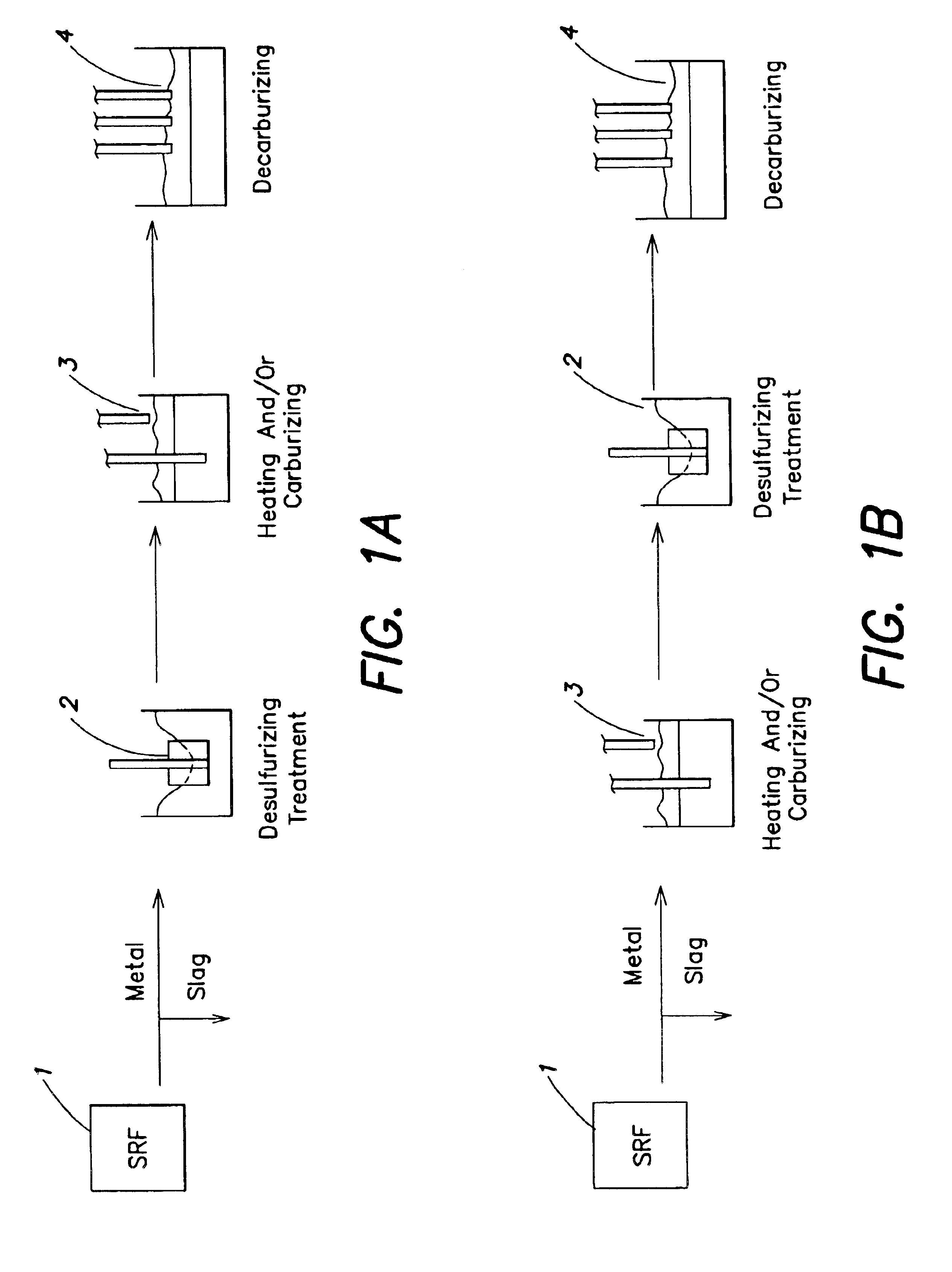
operates the step of heating and / or carburizing the molten iron before or after the desulfurizing step so as to make difference large between the melting point and the temperature of the molten iron. By this treatment, adherence of metal of the low carbon molten iron is improved, and allowable heating margin in a post-process as the decarburization may be secured. The heating and / or carburizing step may be performed before or after the desulfurizing process in the molten iron refining container for desulfurization or other molten iron refining containers.

If the heating and / or carburizing step is operated after the desulfurizing step, the temperature of the same may be lowered than operating before the desulfurization, and the heat loss is small and the wearing of the refractory or bubbling lance can be suppressed. On the other hand, if the heating and / or carburizing step is operated before the desulfurizing step, a hot slag having not been separated from the metal at pouring can be ...

embodiment 2

is the molten iron refining process using the converter typed reacting containers of two or more, desulfurizing the molten iron in at least one converter typed reacting container, and decarburizing the desulfurized molten iron in the converter typed reacting container so as to produce liquid steel. Therefore, the inventive process no longer requires the desulfurization outside furnace conventionally performed excepting an especial case of producing ultra low S steel.

The desulfurizing process and the decarburizing process in Embodiment 2 can be performed using optionally different converter typed reacting containers, and accordingly it is possible to practice the treatments by respectively installing the converter typed reacting container for desulfurization and the converter typed reacting container for decarburization, but the most preferable and useful practicing mode of the invention is to utilize the converter typed reacting containers or two or more including the spare machine ...

example 1

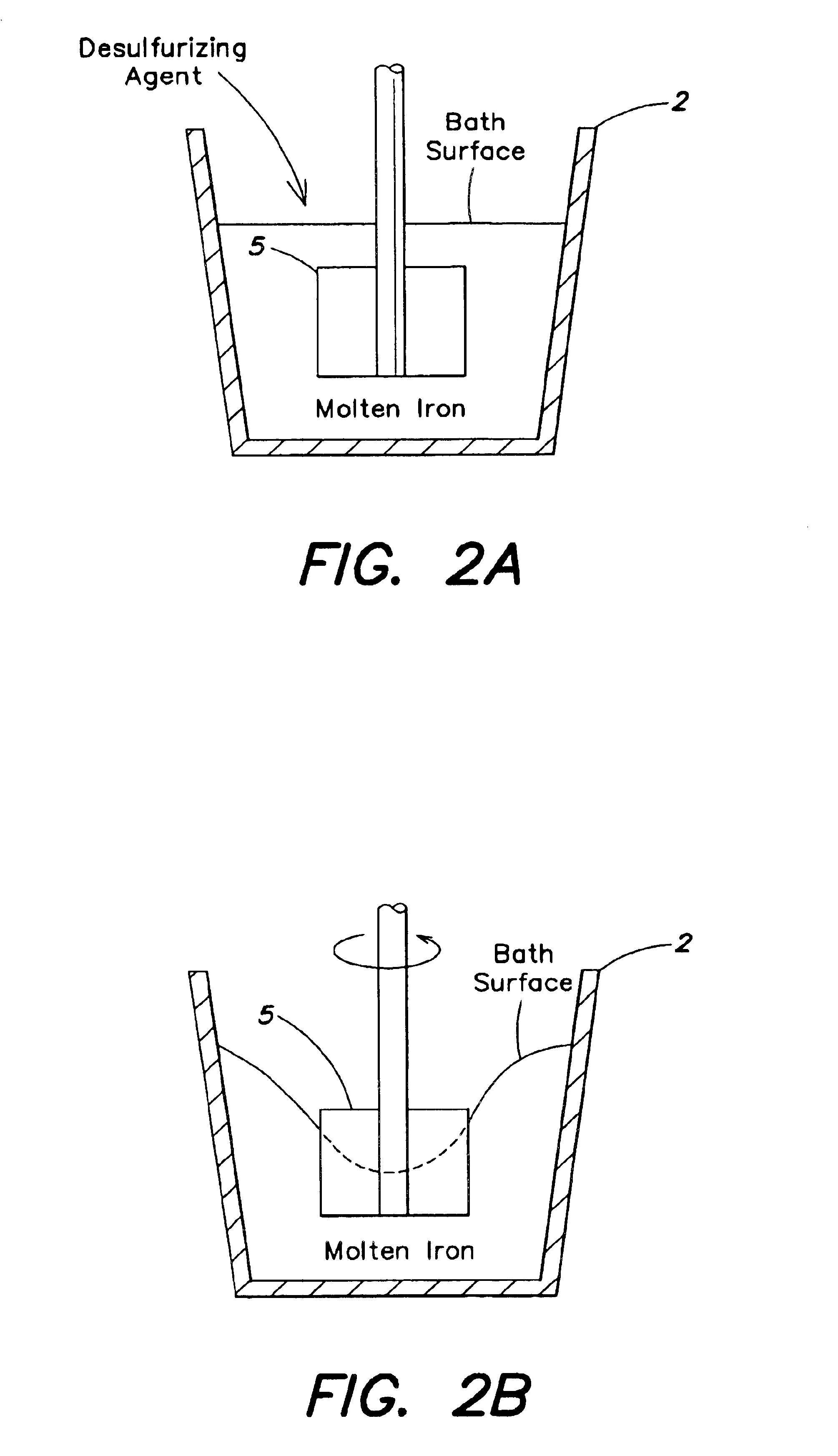
The 100 t molten iron was charged into the 100 t converter (the content volume 90 m3 after laying bricks), the amount of the bottom blowing gas was 0.1 Nm3 / t / min of molten iron, burnt lime of 5 kg / t of molten iron was dropped by gravity, and the desulfurizing treatment was practiced. In this desulfurizing treatment, [S]was decreased from 0.032 wt % to 0.010 wt % for around 15 minutes from starting of the treatment as shown under.

[C][S]Temp. of Molten IronBefore treatment4.5 wt %0.032 wt %1400° C.After treatment4.5 wt %0.010 wt %1360° C.

Subsequently, the desulfurized molten iron was carried out with the decarburizing treatment in another converter, and the steel of [C]: 0.05 wt % and [S]: 0.010 wt % was produced.


PUM

PropertyMeasurementUnit
temperatureaaaaaaaaaa

Abstract

A smelting reduction method comprising (a) charging a carbonaceous material and an ore into a reacting furnace to directly contact the carbonaceous material and the ore; (b) reducing the ore until at least a part of the ore is metallized, the resultant reduced ore containing at least a part of metallized metal being produced; (c) charging the carbonaceous material and the ore containing at least a part of the metallized metal from step (b) into a smelting furnace having a metal bath; and (d) blowing a gas containing 20% or more of oxygen into the metal bath in the smelting furnace to produce molten iron.

Description

FIELD OF THE INVENTIONThe present invention relates to a refining method of molten iron and a smelting reduction method for manufacturing molten iron.BACKGROUND OF THE INVENTIONIn molten iron produced by a smelting reduction method of iron bath type, a carbon level is more often low as 4 wt % or less, and in this case, a melting point is high. In general, the carbon level is 3 to 4 wt %. Hereinafter, the molten iron produced by the smelting reduction method of iron bath type will be called as “smelted and reduced molten iron”. Namely, the melting points of molten iron in general blast furnaces are assumed to be around 1150° C., and if the carbon content is different by 1 wt %, the melting point is different by around 70 to 100° C., and therefore carbon content as in the smelted and reduced molten iron is at a level of 3 wt %, and the melting point is around 1300° C. Metal or slag in the molten iron where the carbon level is low easily adhere troughs or ladles in treatments of molten...

Claims


Application Information

Patent Timeline
Patent Type & Authority Patents(United States)
IPC IPC(8): C21B13/00C21C7/068C21C1/02C21C7/00C21C7/064C21B13/14C21C5/50C21C5/56
CPCC21B13/0013C21B13/14C21C1/02C21C7/068C21C5/56C21C7/0025C21C7/064C21C5/50C21B2100/62C21B2100/66Y02P10/134Y02P10/25
Inventor KAWAKAMI, MASAHIROSAWADA, TERUTOSHISEKIGUCHI, TAKESHIWATANABE, MASAYUKIIWASAKI, KATSUHIROISOZAKI, SHINICHIFUKUMI, JUNICHI
Owner NIPPON KOKAN KK
Why Eureka
Try Eureka