
Method for measuring cellular transmembrane potential changes

Inactive Publication Date: 2005-02-08
MOLECULAR DEVICES
View PDF5 Cites 19 Cited by
  • Summary
  • Abstract
  • Description
  • Claims
  • Application Information

AI Technical Summary

Benefits of technology

[0013](b) A first reagent selected from the potentiometric probes which redistribute from one side of the membrane to the opposite side in response to transmembrane potential; and a second reagent selected from the group consisting of non-fluorescent dyes or pigments that are not membrane-permeable, and absorb the excitation light or emission from the first reagent on one side of the membrane to reduce or eliminate the undesired fluorescence signal; or

Problems solved by technology

Moreover, in conjunction with imaging techniques, these probes can be employed to map variations in membrane potential across excitable cells and perfused organs with spatial resolution and sampling frequency that are difficult to achieve using microelectrodes.
Increased depolarization results in more influx of the anionic dye and thus an increase in fluorescence.
Interactions between anionic oxonols and the cationic K+-valinomycin complex complicate the use of this jonophore to calibrate potentiometric responses.

Method used


Image

  • Method for measuring cellular transmembrane potential changes
  • Method for measuring cellular transmembrane potential changes
  • Method for measuring cellular transmembrane potential changes

Examples


example 1

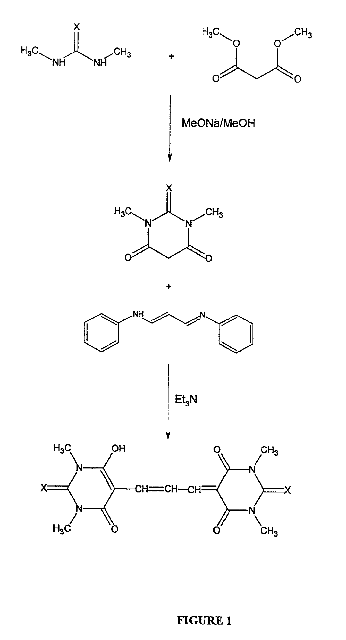
Preparation of DiSBAC1(3)

[0021]

[0022]DiBAC and DiSBAC dyes are prepared based on the procedure for ethyl and butyl derivatives (H. Bartech and G. Haubold, Arch. Pharm. 1982, 315, 761-766). Specifically, malonaldehyde bis(phenylimine)monohydrochloride (2.6 g, 10 mmol) and 1,3-dimethyl-2-thiobarbituric acid (3.5 g, 20 mmol) are dissolved in acetonitrile (40 mL). To the solution is added triethylamine (2 g, 20 mmol). The reaction mixture is refluxed until the starting materials are completely consumed as indicated by TLC. The mixture is cooled to room temperature, and poured into acidic water (pH 2-3, 350 mL). The resulting suspension is filtered to collect the solid that is washed with cold water and air-dried. The crude product is further purified on a silica gel column using a gradient of dichioromethanol / methanol to give the desired product.

example 2

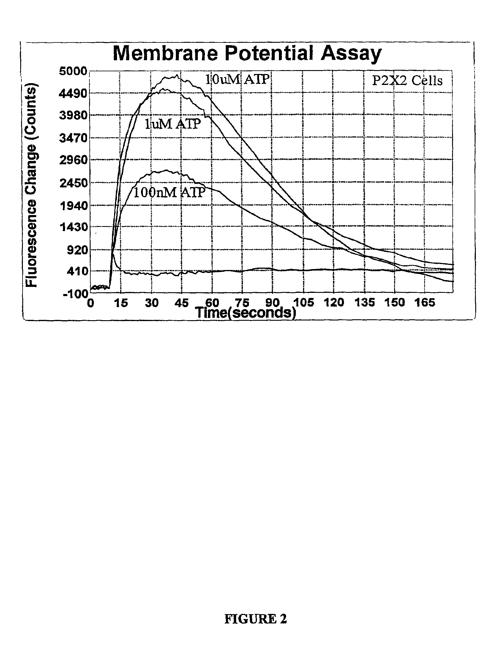
Measuring Membrane Potentials using DiSBAC1(3) in Combination with the Fluorescence Imaging Plate Reader (FLIPR™)

[0023]This specific example illustrates how to use DiSBAC1(3) in P2X2 cells in combination with FLIPR™, fluorescent imaging plate reader sold by Molecular Devices Corp. of Sunnyvale, Calif. P2X2 cells are 1321 N1 astrocytoma cells transfected to overexpress the purinergic P2X2 ligand-gated ion channel. P2X2 belongs to a class of purinergic ion channels that pass calcium and sodium in response to purine, including adenosine 5′-triphosphate (ATP). P2X2 cells are propagated and maintained in DME (high glucose), 10% FCS, 1× Pen / Strep and 2 mM L-glutamine. Doubling time is approximately 36 hours. P2X2 cells should be split at a 1 to 2 ratio upon confluence. The cells should be carried for no more than 20 passages. When approaching this limit, a new frozen vial of cells should be resurrected. Following is a typical kit procedure:[0024]1. Plate 40,000 P2X2 cells in 100 μL per we...

example 3

Measuring Membrane Potentials using DiBAC1(3) in Combination with a Microscope

[0040]DiBAC1(3) is used to measure membrane potential change with a microscope as described by L. M. Loew (Methods in Cell Biology, vol. 38, pp195-209).


PUM


Abstract

The invention encompasses an improved method for measuring membrane potential using compounds of the formula I as potentiometric probes. These probes may be used in combination with other fluorescent indicators such as Indo-1, Fura-2, and Fluo-3, such probes may be used in microplate reading devices such as FLIPR™, fluorescent imaging plate reader, sold by Molecular Device Corp., of Sunnyvale, Calif.; flow cytometers; and fluorometers. Such probes are used to measure membrane potential in live cells

Description

BACKGROUND OF THE INVENTION[0002]1. Field of the Invention[0003]The present invention relates generally to the fields of biology and chemistry, and bioanalytical instrumentation. In particular, the present invention is directed to composition and methods for use in sensing membrane potentials, especially in biological systems. Potentiometric optical probes enable researchers to perform membrane potential measurements in organelles and in cells that are too small to allow the use of microelectrodes. Moreover, in conjunction with imaging techniques, these probes can be employed to map variations in membrane potential across excitable cells and perfused organs with spatial resolution and sampling frequency that are difficult to achieve using microelectrodes.[0004]2. Background of the Art[0005]The plasma membrane of a cell typically has a transmembrane potential of approximately −70 mV (negative inside) as a consequence of K+, Na+ and Cl− concentration gradients that are maintained by a...

Claims


Application Information

Patent Timeline
IPC IPC(8): G01N33/52
CPCG01N33/52Y10S435/975
Inventor KLAUBERT, DIETERDIWU, ZHENJUNYI, GUOLIANGKIRK, MARTIN
Owner MOLECULAR DEVICES
Learn More