
Passive remote sensor of chemicals

a remote sensor and chemical technology, applied in the field of passive, remote device and method for detecting chemicals, can solve the problems of inability to take measurements, undesirable limitation, and serious concern about the possibility of dangerous substances being released, and achieve the effect of reducing or eliminating common background noise components

Inactive Publication Date: 2005-02-08
UNIV OF VIRGINIA ALUMNI PATENTS FOUND
View PDF8 Cites 129 Cited by
  • Summary
  • Abstract
  • Description
  • Claims
  • Application Information

AI Technical Summary

Benefits of technology

In another embodiment of the remote sensor of the present invention, a sample filter assembly is positioned in the first optical path, the sample filter assembly including a notch filter (a filter which blocks one frequency or a range of frequencies but transmits the rest of the spectrum). The sample notch filter may be configured to attenuate at a frequency that coincides with a selected spectral line of a target species, and the second optical path may include no filter at all and therefore provide no attenuation. Alternatively, accuracy may be improved by positioning a blank in the second optical path, the blank being made of the substrate of the sample notch filter. In addition, a bandpass filter with a frequency center that coincides with the sample notch filter may be placed either in front of both the first and second optical paths before the sample notch filter and blank, or after both the sample notch filter and blank.

Problems solved by technology

Indeed, the potential release of dangerous substances is now a serious concern not only for the military, but for local governments as well.
This is an undesirable limitation, and can be dangerous if the target gas is toxic.
In addition, these systems are only capable of taking measurements in a point-wise fashion, such that numerous measurements are required to determine the boundaries of a chemical cloud.
The SAW system is also portable and offers the exceptionally high sensitivity of 0.2 mg / m3, but lacks specificity and cannot determine the specific identity of a gas (i.e., it can only determine any of a certain number of gases may be present).
The DIAL and other lidar systems suffer from, among other things, a dependance on a narrowband, rapidly tunable laser system.
Consequently, they are extremely complex and expensive, require highly trained personnel for operation, and provide an undesirably limited field of view (FOV) (which is delimited in such systems by the divergence of the laser beam).
In addition to these disadvantages, the filter and detector components of the Air Force's LARS CO2 DIAL system must be cooled in a liquid nitrogen environment.
Accordingly, the signal is weaker than that of the DIAL systems and the range is limited.
The main disadvantage of FTIR systems, including the RSCAAL system, is that they depend on a complete spectral scan followed by detailed analysis of the spectrum.
To accomplish that scan, the system requires a complex, highly refined mechanical tunning arrangement which is difficult to make sufficiently rugged for field applications.
However, they also require longer scans and much larger data storage and processing capabilities than multispectral-based systems, and therefore are less useful for operation by untrained personnel or from fast moving platforms.
But biasing the acousto-optic element during the tuning process causes the image to shift slightly, thereby complicating correlation between images obtained at different wavelengths.
However, fielding a Fabry-Perot filter is complicated by the need for good alignment and spacing control between the moving mirrors.
But cross talk between its spectral images can compromise its specificity.
The time required to acquire these images is usually limited by the maximum imaging rate of available FPAs, which presently stands at ≦50 Hz.
The primary drawback of GFCRs is the need for the sensor to include a cell containing the sample species, which may present a hazard when the sensor is to be used for the detection of toxic chemicals or chemicals that are difficult to handle.
In addition, the requirement of a separate cell for each target chemical results in a bulky detector.
Moreover, the need to mechanically switch the cells in and out of the FOV significantly reduces system reliability and speed, and may prevent the imaging of proliferated chemicals, such as gas clouds or liquid spills, due to a loss of registration between consecutive images.
Although this approach avoids the unreliability associated with mechanically switching between the cells, it is undesirably complex and expensive, requiring the use of a polarization modulator, two polarization beam-splitters, and a waveplate.
In addition, the performance of available polarizing beam splitters in the 8-13.3 μm spectral range presently is not sufficient to develop a sensitive detector of the design of the '797 patent for use in the 8-13.3 μm range.
While attempting to address this disadvantage, however, the grating-based design of the '571 patent introduces a number of additional disadvantages.
The slit is also used to reduce interferences by stray light, to which the grating-based system is particularly susceptible.
Without such a slit, the system loses some of its spectral resolving capabilities.
Consequently, the light gathering capability or FOV of the grating-based GFCR system is limited by the slit width.
The slit required by the design of the '571 patent also prevents the possibility of imaging the spatial distribution of chemical clouds.
Given the optics required, the fact that the system is sensitive to optical alignment between the grating and the slit, and the fact that the system requires sufficient optical path for the proper grating dispersion to develop (which may require up to several centimeters of distance between the grating and slit), the grating-based GFCR system clearly is not capable of miniaturization.
A significant additional disadvantage, however, is that the need for a combination of a concave grating and spatial filter assemblies renders the system complex and cumbersome.
Although the technique of the '654 patent purports to provide well-defined spectral signatures, as well as capabilities of imaging preprogrammed species, it is exceptionally complex and, depends heavily on fine optical alignment which can affect the spectral resolution and the registration between images that are designed to represent the species itself and images that are representative of its background.
This approach is disadvantageous, however, as it depends on an exceptionally broad bandwidth, which results in an undesirably low specificity.
In addition, the Althouse, et al. design suffers from undesirably low sensitivity because it fails to recognize the need for a background subtraction and normalization technique.
Disadvantageously, the design requires that the filters be cryogenically cooled.
In addition, the design does not provide for methods to correct for the effects of background radiation or emission, or absorption by atmospheric or other background species.
Furthermore, the use of a mechanical filter wheel to switch between the filters reduces the reliability of the system and prevents miniaturization.
In addition, the use of moving filters inherently leads to a loss of registration between the images obtained through the two different filters, thereby preventing the possibility of subtracting one image from the other.
The Wimmers, et al. method also does not contemplate correcting for background interferences.

Method used


Image

  • Passive remote sensor of chemicals
  • Passive remote sensor of chemicals
  • Passive remote sensor of chemicals

Examples


Embodiment Construction

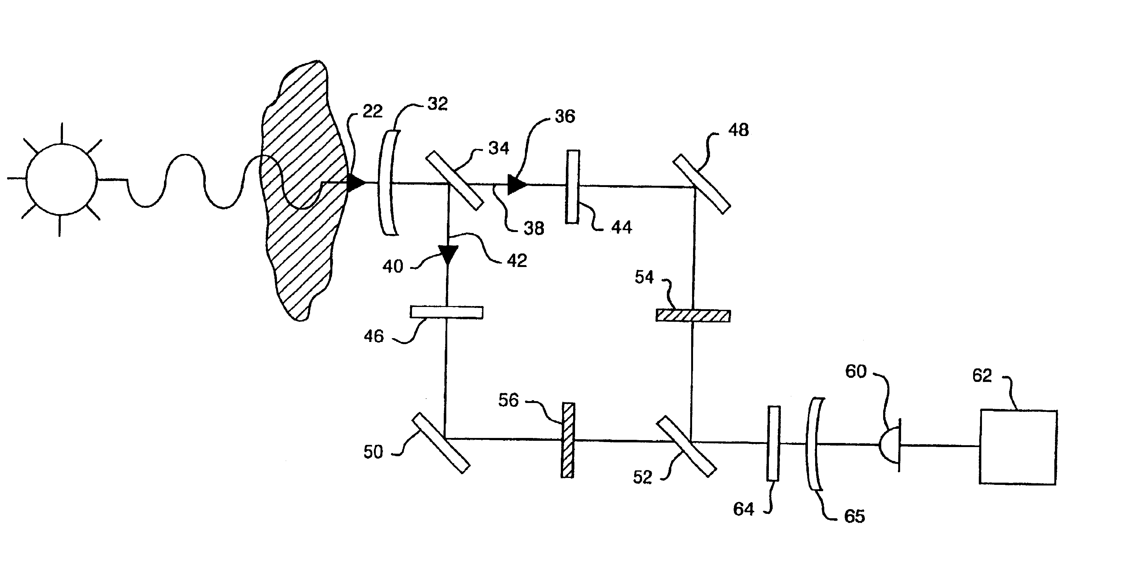
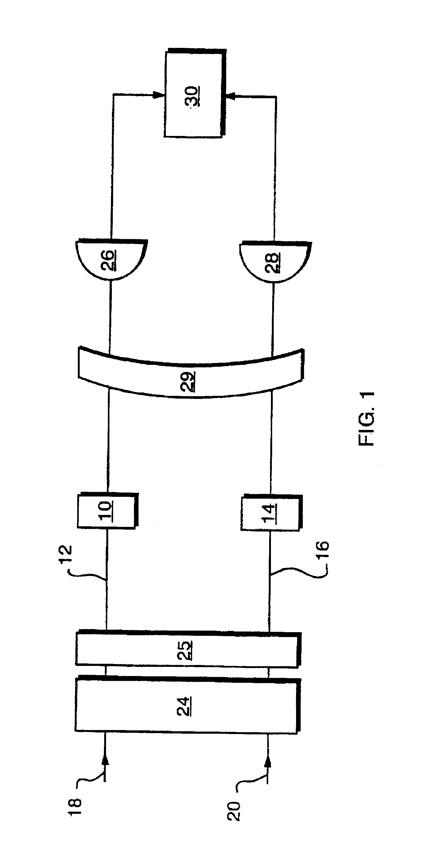
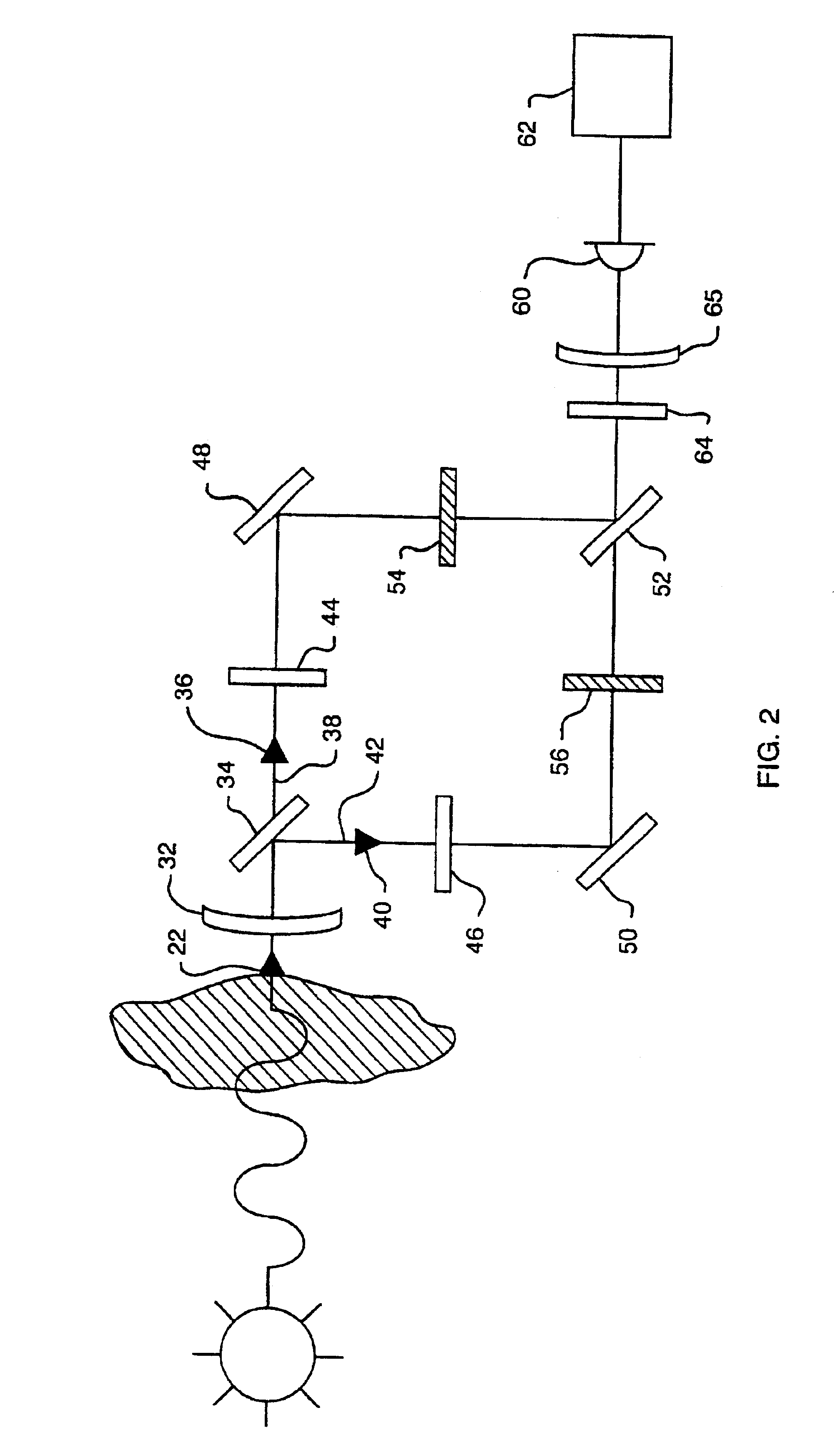
As illustrated schematically in FIG. 1, the sensor of the present invention generally comprises a first filter assembly 10 positioned in a first optical path 12, and a second filter assembly 14 positioned in a second optical path 16. First and second optical paths 12 and 16 may correspond to wholly separate first and second beams of incident light 18 and 20, as shown in FIG. 1, or may correspond to beams derived from a single incident light beam 22, as illustrated in connection with the embodiments of FIG. 2. The term “light,” as used throughout the present application, is intended to include any wavelength of optical radiation, regardless of source, from the ultraviolet (UV) through the infrared (IR) regions of the spectrum.

The incident light beam to be detected typically is the product of the absorption or emission spectra by a target chemical species. For absorption, radiation from artificial sources such as lamps, lasers, glow bars, light emitting diodes, or black body sources, ...


PUM


Abstract

A remote sensor for use as a handheld, mobile or stand-alone sensor has first (12) and second (16) optical paths, light collecting optics, a sample filter (10) assembly positioned in a first optical Path (12), a reference filter (14) assembly positioned in a second optical path (16), a detector assembly to detect the filtered light r other radiation, and a detector output comparison device such as BRD to minimize the effects of common background noise components, differences in light or other radiation source power, and absorption or emission by interfering species.

Description

FIELD OF THE INVENTIONThe present invention relates to a passive, remote device and method for detecting chemicals. More particularly, the present invention relates to a passive, remote device and method using differential absorption radiometer (DAR) or notch filter correlation radiometer (NFCR) technology to detect chemicals including gases, liquids, solids and adsorbents.BACKGROUND OF THE INVENTIONThere is an ongoing need for devices and methods capable of the early, passive remote detection of dangerous gases and other substances. Recently, the need for such systems has been heightened by the spread of chemical warfare technology around the world and the increasing number of acts of global terrorism. Indeed, the potential release of dangerous substances is now a serious concern not only for the military, but for local governments as well.The development of passive remote detectors has also been driven by other factors, such as the growing concern for the effects of industrial and...

Claims


Application Information

Patent Timeline
IPC IPC(8): G01N21/31G01N21/35
CPCG01N21/3504G01N21/314
Inventor LAUFER, GABRIEL
Owner UNIV OF VIRGINIA ALUMNI PATENTS FOUND
Learn More