
Chemical mechanical polishing slurry

a technology of mechanical polishing and slurry, applied in the direction of lapping machines, polishing compositions, other chemical processes, etc., can solve the problems of high probability of gate electrode damage, uneven thickness of inter-silicon oxide layer, shortening unless corrected, etc., to and reduce the removal rate of oxide layer and nitride layer. , the effect of significant reduction

Inactive Publication Date: 2005-02-15
SAMSUNG ELECTRONICS CO LTD
View PDF6 Cites 13 Cited by
  • Summary
  • Abstract
  • Description
  • Claims
  • Application Information

AI Technical Summary

Benefits of technology

To solve the above problems, it is an objective of the present invention to provide a polishing slurry that reduces the removal rates of a silicon oxide layer and a silicon nitride layer, which are exposed and etched together during a CMP of the entire polysilicon layer for forming a polysilicon plug.
It is another objective of the present invention to provide a polishing slurry, in which the removal rate of a silicon oxide layer exposed and etched during an additional CMP process of a polysilicon layer for preventing a short of a polysilicon plug, is higher than the removal rate of a silicon nitride layer, while the layers are being etched simultaneously.
Accordingly, to achieve these and other objectives, there is provided a polishing slurry including an abrasive, deionized water, a pH controlling agent, and polyethylene imine (PEI), having a molecular structure of [—CH2CH3N(CH2CH2NH2)—]x[—CH2CH2NH2—]y, where x and y are positive integers, and where x or y could be zero as well. Using this polishing slurry, the removal rates of the silicon oxide layer and the silicon nitride layer, simultaneously exposed during CMP of a conductive layer such as a polysilicon layer, can be controlled, that is, reduced relative to the removal rate of the polysilicon layer.
If a choline derivative is further included in the polishing slurry including polyethylene imine, there is a synergetic effect for reducing the removal rates of the oxide layer and the nitride layer. If the choline derivative is included, even if the amount of polyethylene imine is less than 0.2 wt %, the effect of reducing removal rates of the oxide layer and the nitride layer is significant. The choline derivative can be one selected from the group consisting of choline chloride, choline base, choline bromide, choline iodide, choline dihydrogen citrate, choline bitartrate, choline bicarbonate, choline citrate, choline ascobate, choline borate, choline theophyllinate, choline gluconate, acethylcholine chloride, acetylcholine bromide, and methacholine chloride.
In particular, if a polishing slurry including polyethylene imine of about 0.5 wt %, and the choline chloride of about 1.3 wt %, is used, removal rates of a silicon oxide layer and a silicon nitride layer are maintained at a low state during CMP of a polysilicon layer, but the removal rate of the silicon oxide layer is slightly greater than the removal rate of the silicon nitride layer, so that the slurry including the polyethylene imine and the choline derivative can be effectively utilized for forming a plug and separating a node using a CMP process along the entire surface.

Problems solved by technology

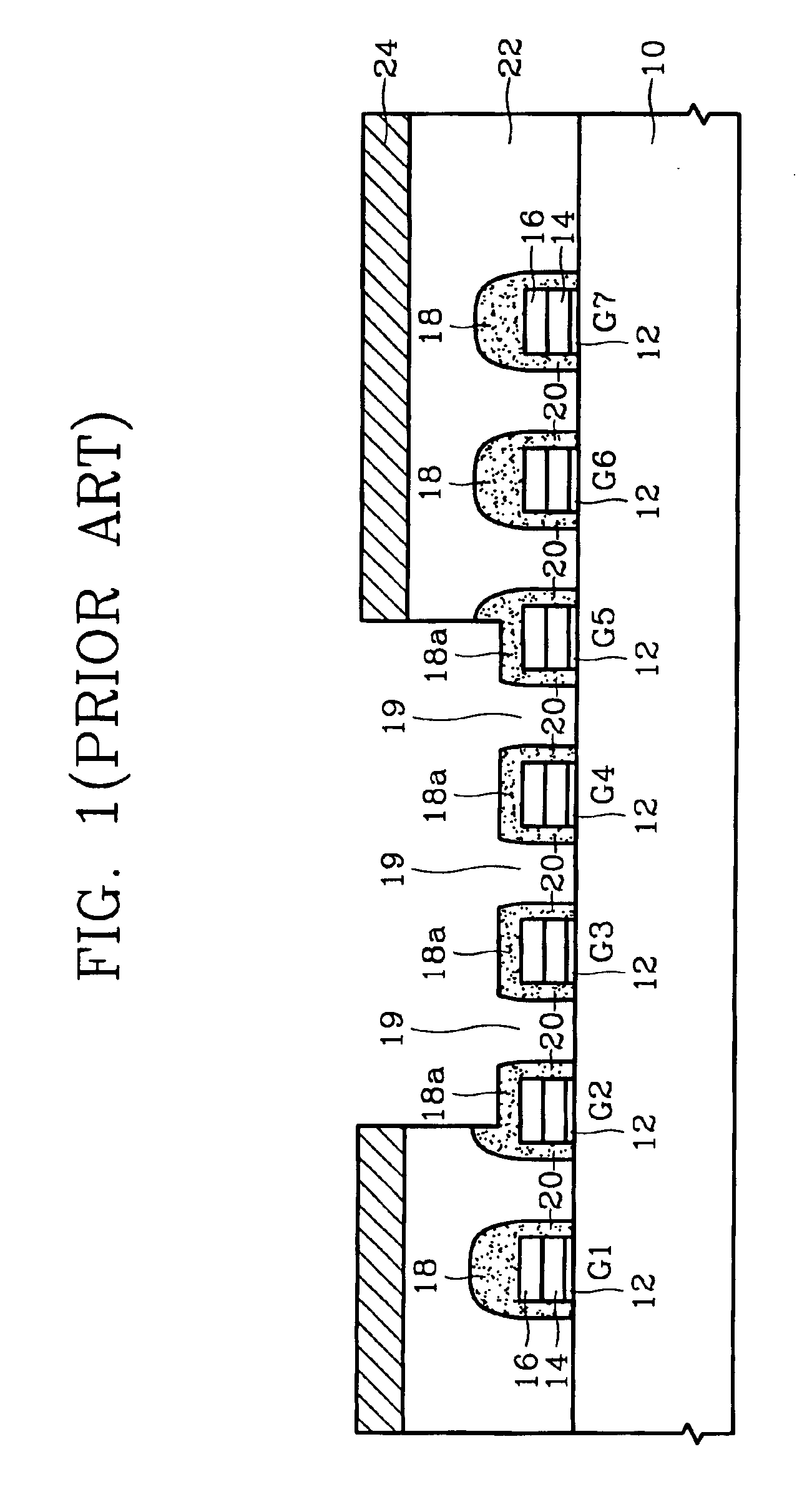
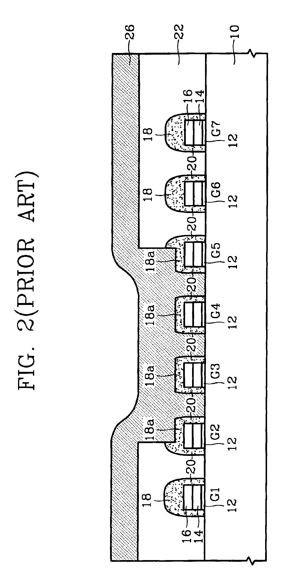
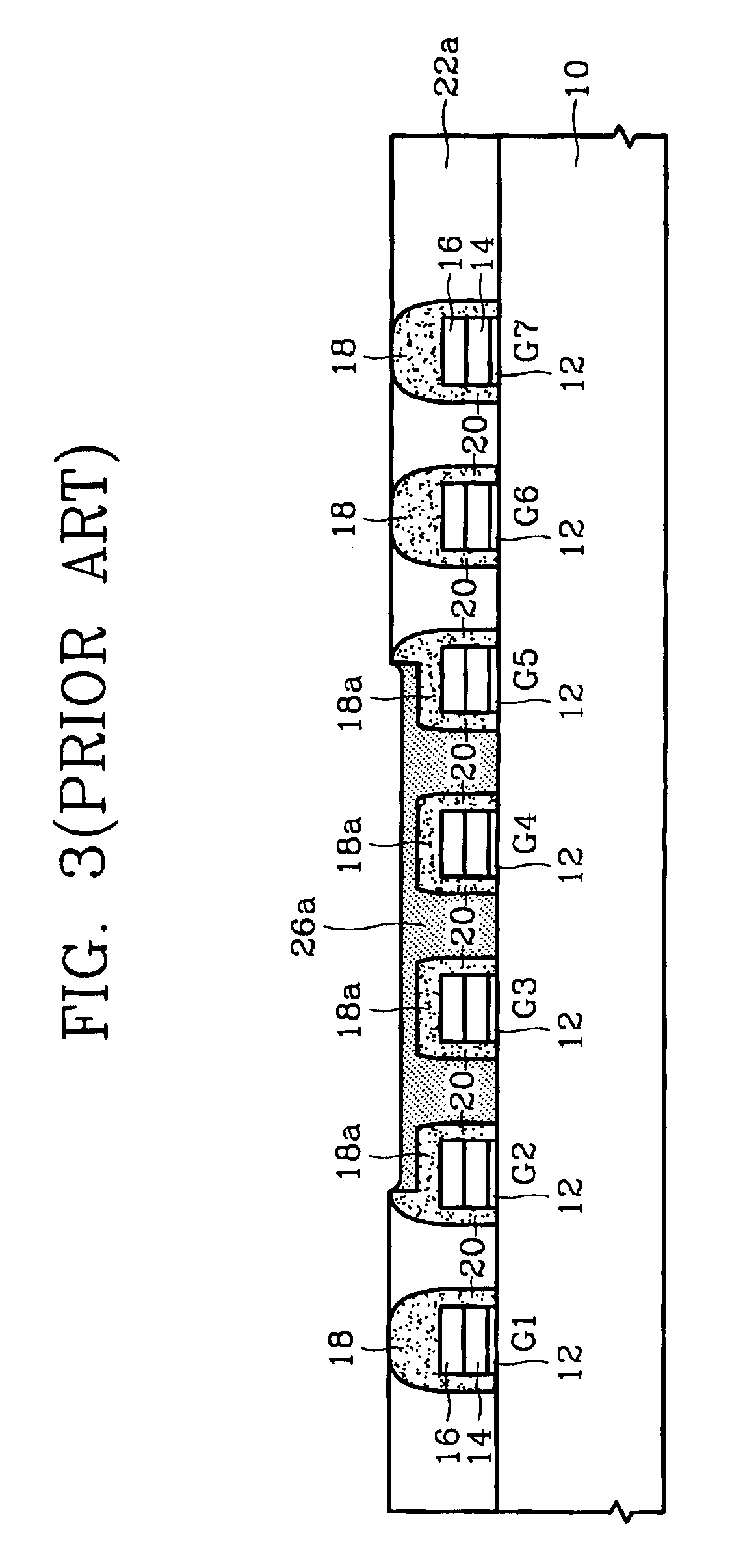
However, in this example, a problem exists in that the thickness of the inter-silicon oxide layer is not uniform after the partial CMP, which in turn causes additional problems after a full CMP is performed.
In other words, the contact holes are not “separated”, which can cause shorts unless corrected.
As shown in Table 1, since the removal rates of the silicon oxide layer and the silicon nitride layer, which are removed together during the removal of the polysilicon layer, are large, the probability is high that the gate electrodes will be damaged, and it is thus difficult to secure a CMP process margin of the polysilicon layer.
However, this increases the cost and time to produce a device.

Method used


Image

  • Chemical mechanical polishing slurry
  • Chemical mechanical polishing slurry
  • Chemical mechanical polishing slurry

Examples


example 1

In this example, the polishing slurry included the well known SS-25 base polishing slurry manufactured by the Cabot Co., which was diluted with deionized water at a ratio of 1:1. The downward force of a polishing head of a polisher manufactured by the Presi Co. was set at 5 psi, and the speed of the polishing table was set at 65 rpm. Then, the removal rate of Si3N4 and PE-TEOS with respect to changes in the amount of PEI was investigated. The results are shown in Table 2. Here, PE-TEOS is formed by PE-CVD, and Si3N4 is formed by LPCVD. The SS-25 includes an abrasive of fumed silica of 35 wt %, a pH controlling agent (pH=11) and deionized water as the main ingredients.

TABLE 2Removal Rate of Si3N4 and PE-TEOS as a Function of PEI AmountPE-TEOS removal ratePEI amount (wt %)(Å / mm)Si3N4 removal rate (Å / min) 0.0 wt %2778647 0.2 wt %2918611 0.5 wt %1523341.25 wt %6972

The wt % amount of PEI is relative to a mixture including the SS-25 slurry and PEI. As shown in Table 2, the removal rates o...

example 2

In this example, Table 3 investigates the situation where the removal rates of PE-TEOS and Si3N4 are determined with respect to a dilution amount of deionized water, where PEI is not added to the base slurry SS-25. Table 4 investigates the situation where the removal rates of PE-TEOS and Si3N4 are determined with respect to a dilution amount of deionized water, where PEI is added to the base slurry SS-25. As in Example 1, the Table 3 and 4 values were produced on an apparatus in which the downward force of the Presi polishing head was set at 5 psi, and the speed of the polishing table was set at 65 rpm.

The results of Table 3 were obtained using a first dilution ratio (polishing slurry SS-25: deionized water) of 1:1, a second dilution ratio of 1:3, and a third dilution ratio of 1:7. In these examples, the polishing slurry in the first case includes an abrasive in the amount of 12.5 wt %, in the second case it includes an abrasive in the amount of 6.25 wt %, and in the third case it i...

example 3

In this example, Table 5 investigates the situation of the removal rates of PE-TEOS and Si3N4 where PEI is added to the base slurry SS-25, and further including a choline derivative. As in Example 1, the Table 5 values were produced on an apparatus in which the downward force of the Presi polishing head was set at 5 psi, and the speed of the polishing table was set at 65 rpm.

TABLE 5Removal Rate of Si3N4 and PE-TEOS as a Function ofPEI and Choline Derivative AddedSS-25 +SS-25 +0.5 wt %PolishingSS-25 +1.3 wt %PEI + 1.3 wt %slurry type 0.5 wt % PEIcholine chloride choline chlorideLayer typePE-TEOSSi3N4PE-TEOSSi3N4PE-TEOSSi3N4Removal15233420552571914rate(Å / min)

First, by comparing Table 1 and Table 5, note that if a choline derivative (e.g., choline chloride) is added to general polishing slurry, for example SS-25, the removal rate of PE-TEOS (a silicon oxide layer), does not change very much from 2501 to 2055 Å / min. However, the removal rate of Si3N4 (a silicon nitride layer), is greatl...


PUM

PropertyMeasurementUnit
wt %aaaaaaaaaa
pHaaaaaaaaaa
molecular structureaaaaaaaaaa

Abstract

A polishing slurry including an abrasive, deionized water, a pH controlling agent, and polyethylene imine, can control the removal rates of a silicon oxide layer and a silicon nitride layer which are simultaneously exposed during chemical mechanical polishing (CMP) of a conductive layer. A relative ratio of the removal rate of the silicon oxide layer to that of the silicon nitride layer can be controlled by controlling an amount of the choline derivative.

Description

BACKGROUND OF THE INVENTION1. Field of the InventionThe present invention relates to a polishing slurry used for a chemical mechanical polishing (CMP) process, and more particularly, to a polishing slurry which allows for control of removal rates of a silicon oxide layer and a silicon nitride layer exposed during polishing of a polysilicon layer.2. Description of the Related ArtSemiconductor devices are comprised of numerous integrated circuits, which are produced by selectively and repeatedly performing a series of photographic, etching, diffusive, metal deposition, and other process steps. For example, plasma enhanced-chemical vapor deposition (PE-CVD) processes and reactive ion etch (RIE) processes are used to fully form device patterns that are pre-set on the wafer.During the semiconductor device manufacturing process, a chemical mechanical polishing (CMP) process is typically used for horizontally planarizing various kinds of layers, such as oxide layers, nitride layers, metal ...

Claims


Application Information

Patent Timeline
Patent Type & Authority Patents(United States)
IPC IPC(8): C09G1/00C09G1/02H01L21/02H01L21/321B24B37/00C09C1/68C09K3/14H01L21/304
CPCH01L21/3212C09G1/02C09K3/14
Inventor LEE, JAE-DONGYOON, BO-UNHAH, SANG-ROK
Owner SAMSUNG ELECTRONICS CO LTD
Learn More