Optical interferometer generating a mode-locked laser oscillation, all-optical switch, all-optical asymmetric demultiplexer and all optical pulse reshaping apparatus

a mode-locked laser and interferometer technology, applied in the field of optical elements, can solve the problems of difficult implementation of light receiving elements, complex and large structure of optical asymmetric demultiplexing signal processing system, and inability to achieve the response speed required to detect optical signals

Inactive Publication Date: 2005-02-15
FUJITSU LTD
View PDF5 Cites 4 Cited by
  • Summary
  • Abstract
  • Description
  • Claims
  • Application Information

AI Technical Summary

Benefits of technology

It is a general object of the present invention to provide a novel and us...

Problems solved by technology

In this case, since the response speed of the electric signal is restricted by the traveling time of a carrier in a photo diode used for the photoelectric conversion, it is impossible to achieve the response speed required to detect the optical signal even if a high-speed PIN photo diode is used.
However, the above method is not preferred with respect to the fabrication cost in that the optical asymmetric demultiplexing signal processing system 10 has the complicated and large structure because the optical asymmetric demultiplexing signal processing system 10 includes the conversion process to temporarily convert the input optical signal into the electric signal.
Additionally, it is difficult to implement a light receiving element for detecting the high-speed optical signal traveling at 160 Gbit/s under such a structure.
Obviously, it is difficult to integrate the two parts in practice.
Additio...

Method used


Image

  • Optical interferometer generating a mode-locked laser oscillation, all-optical switch, all-optical asymmetric demultiplexer and all optical pulse reshaping apparatus
  • Optical interferometer generating a mode-locked laser oscillation, all-optical switch, all-optical asymmetric demultiplexer and all optical pulse reshaping apparatus
  • Optical interferometer generating a mode-locked laser oscillation, all-optical switch, all-optical asymmetric demultiplexer and all optical pulse reshaping apparatus

Examples


sixth embodiment

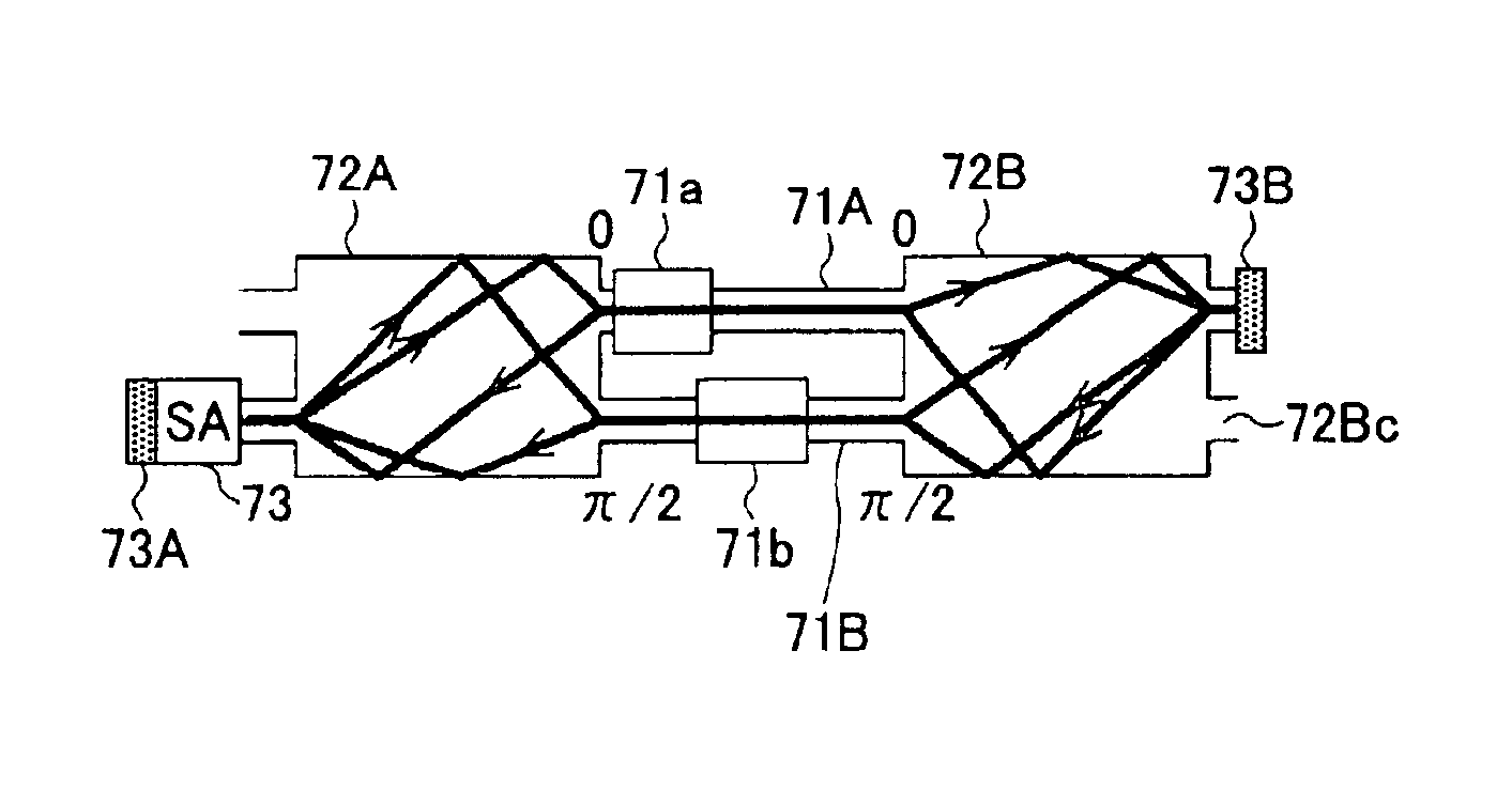
A description will now be given of a control method of the mode-locked higher harmonic that is used under the present invention and an optical asymmetric demultiplexer, which adopts the control method therein, according to the present invention.

Regarding a normal mode-locked laser, the order of a higher harmonic of the mode-locked light increases as a more amount of current is injected to a gain medium. Thus, it is possible to obtain a desired order of higher harmonic of the mode-locked light without the use of a special structure. However, if a certain structure to be mentioned in the following is adopted, it is possible to stable an operation of the mode-locked laser.

FIGS. 20A and 20B show two cases regarding the control method of the mode order of a mode-locked laser by using a colliding mode lock. One is the case in which an end surface of an optical cavity is covered with a high reflective film. The other is the case in which an end surface of an optical cavity is not covered w...


PUM


Abstract

An all-optical switch, an all-optical signal waveform reshaping element and an all-optical asymmetric demultiplexer are formed of an optical interferometer having a compact and simple structure. Nonlinear gain media are provided at positions different from each other in two arms of a Mach-Zehnder optical interferometer. Then, an optical cavity is formed by mounting a mirror on an optical input-output port in each of a first and a second multi-mode optical interferometers connected with the two arms. Furthermore, when a saturable absorption medium is placed on the mirror of one of the multi-mode optical interferometers, a mode-locked laser oscillation is induced.

Description

GROSS REFERENCE TO RELATED APPLICATIONSThe present application is based on Japanese priority application No. 2001-383725 filed Dec. 17, 2001, the entire contents of which are hereby incorporated by reference.BACKGROUND OF THE INVENTION1. Field of the InventionThe present invention generally relates to optical communication arts, and more particularly to an optical element that serves for a high-capacity optical communication and achieves stable performance with a simple structure.2. Description of the Related ArtIn recent high-capacity optical communication arts, WDM (Wavelength Division Multiplexing) is typically used to deal with large traffic volume. In the WDM, optical signal components each of which has a different wavelength from each other are formed in correspondence with a large number of signals, and these optical signal components are multiplexed to form a single wavelength multiplexed optical signal.On the other hand, in order to further increase a communication capacity...

Claims


Application Information

Patent Timeline
IPC IPC(8): G01B9/02G02B6/34H01S5/06H01S5/00H01S5/50H01S5/065H01S5/10G02F1/017G02F1/365H01S5/0625
CPCH01S5/14H01S3/07H01S3/082H01S3/1118H01S5/0657H01S3/10092
Inventor MUKAI, KOHKI
Owner FUJITSU LTD
Why Eureka
Try Eureka