
Method and device for carrying out frequency synthesis in a distance measuring device

a distance measuring and frequency synthesis technology, applied in the direction of distance measurement, pulse technique, instruments, etc., can solve the problems of only, if at all, being able to supress at extraordinarily high filtration effort and expense, and unable to achieve the effect of reducing the phase noise of the ring oscillator, low energy consumption, and low cos

Inactive Publication Date: 2005-02-22
LEICA GEOSYSTEMS AG
View PDF27 Cites 57 Cited by
  • Summary
  • Abstract
  • Description
  • Claims
  • Application Information

AI Technical Summary

Benefits of technology

A method and an apparatus are to be furnished with which the high frequencies required for the modulation frequency and for the mixer frequency can be generated simply and economically. The generation of the high frequencies should be done with the requisite precision and should have low current consumption, so that their use with handheld devices remains assured. The frequency generator should require only little space, so that the size of the device can be reduced. Advantageously, the design of the frequency generator should enable economical, replicable mass production.
A distance measuring device equipped according to the invention and based on the principle of phase measurement has an emitter for emission of an optical radiation, a receiving optical system for the optical measurement radiation remitted or scattered by an object to be measured, a photoelectric receiver downstream of the receiving optical system for converting the optical radiation into electrical measurement signals, and a signal processing system for comparing the measurement signals with reference signals and examining them for their phase relationship in order from that to determine the distance from the object being measured and make the result available to the user. The emitted radiation is modulated with a high-frequency modulation frequency. A high-frequency mixer frequency deviates from the modulation frequency by the frequency of the low-frequency measurement signal to be evaluated and superimposed on it is the electrical signal furnished by the receiver. The means for generating a high-frequency modulation frequency for the emitted optical radiation and a high-frequency mixer frequency, which differs from the modulation frequency and on which the electrical signals furnished by the photoelectric receiver can be superimposed, are embodied in accordance with the invention or one of its modifications. This makes the production of the distance measuring device less expensive. Its dimensions can be kept small. Particularly in an integrated embodiment of the means for generating the high frequencies on one or more semiconductor components, preferably made by CMOS technology, the device also has reduced energy consumption. This is a major advantage, above for battery-operated handheld devices.

Problems solved by technology

With such high frequencies located so close together, unwanted sidebands, however, can only, if at all, be supressed at extraordinarily high filtration effort and expense.
Such provisions are expensive and often create further sources of error.
To assure the close tolerances, complicated and expensive production methods are required.
For modulation frequencies greater than 100 MHz, additional frequency multipliers are needed, which entail additional costs.
However, the method is very complicated in terms of circuitry, and because of the many electronic components required, it has high current consumption.
This is a decisive disadvantage, however, especially for relatively inexpensive handheld devices.

Method used


Image

  • Method and device for carrying out frequency synthesis in a distance measuring device
  • Method and device for carrying out frequency synthesis in a distance measuring device
  • Method and device for carrying out frequency synthesis in a distance measuring device

Examples


Embodiment Construction

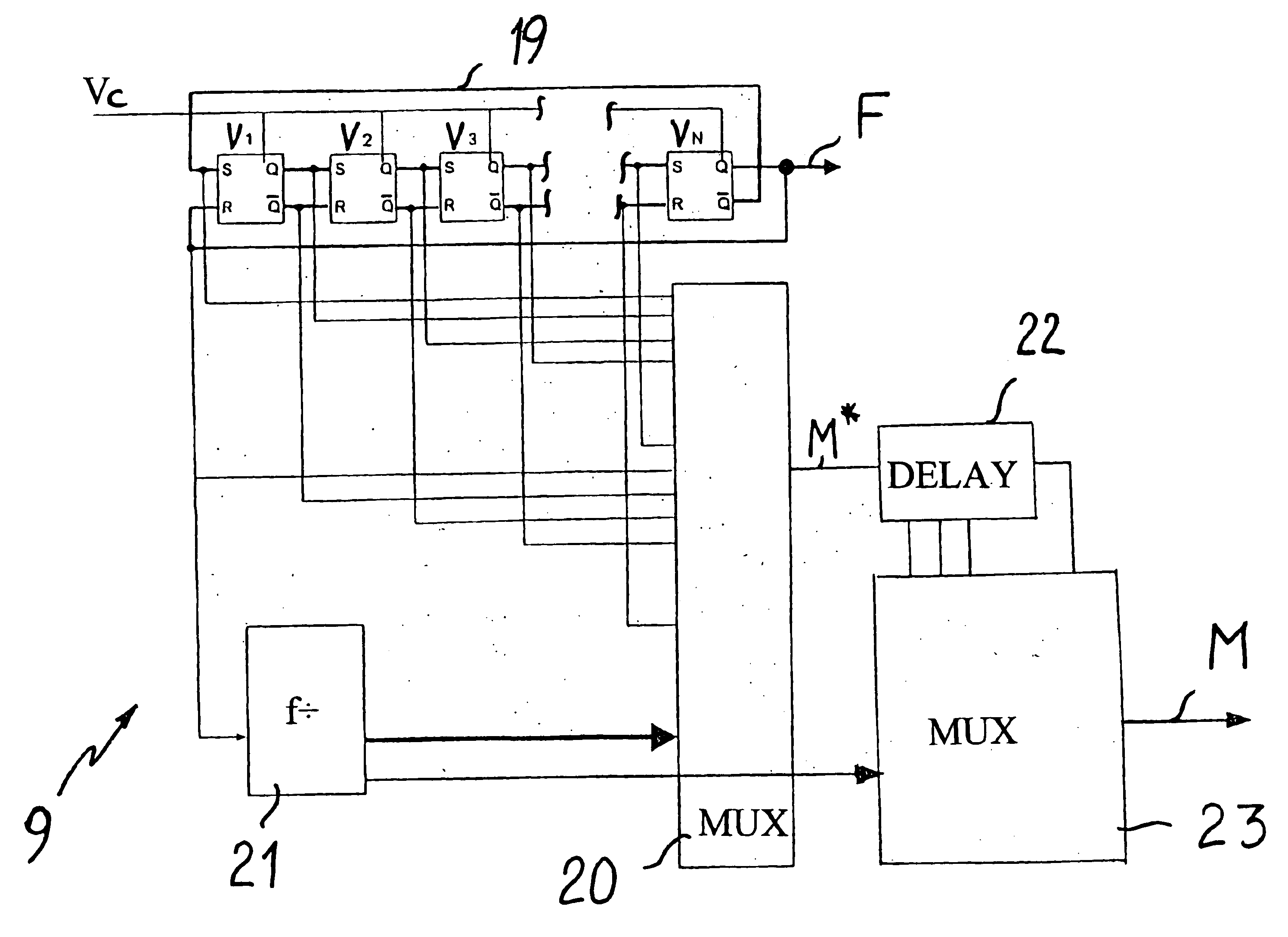
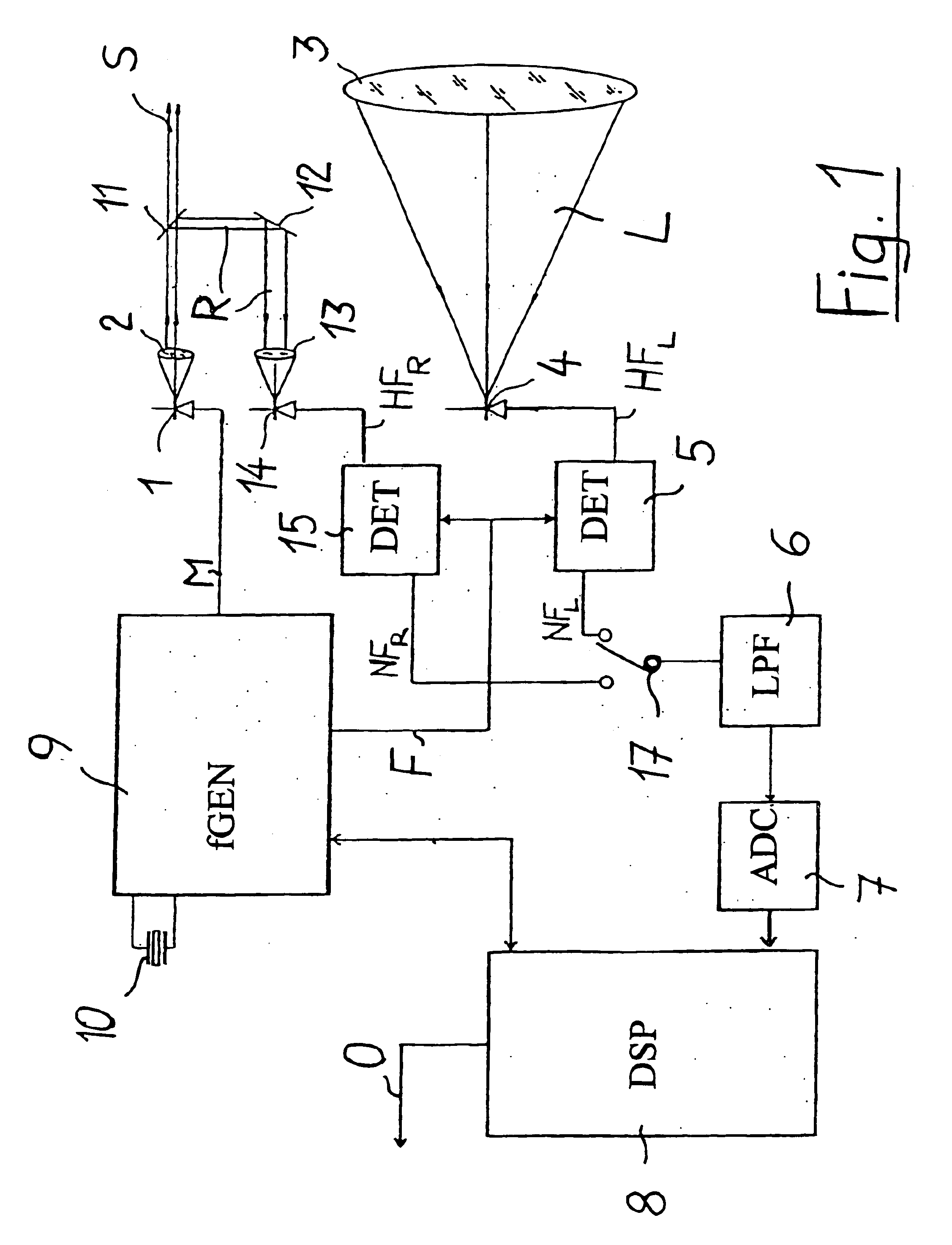
In FIG. 1, one example of a distance measuring device is shown, which is equipped with a device according to the invention for carrying out frequency synthesis. The distance measuring device has a laser source 1, which preferably emits visible laser radiation. The emitted laser radiation, collimated by a collimating optical system 2, is split by a beam splitter 11 into a measurement beam S and as a reference beam R. As an example, a partly transparent mirror can be used as the beam splitter 11. The measurement beam S reaches a measurement object whose distance from the distance measuring device is to be measured. The radiation L remitted or scattered by the measurement object is collected by a receiving optical system 3 and carried to a measuring receiver 4. A pin photodiode can be used, for instance, as the measuring receiver 4. The reference beam R is deflected by a deflecting mirror 12 and collected by an optical system 13 and carried to a reference receiver 14. The reference rec...


PUM


Abstract

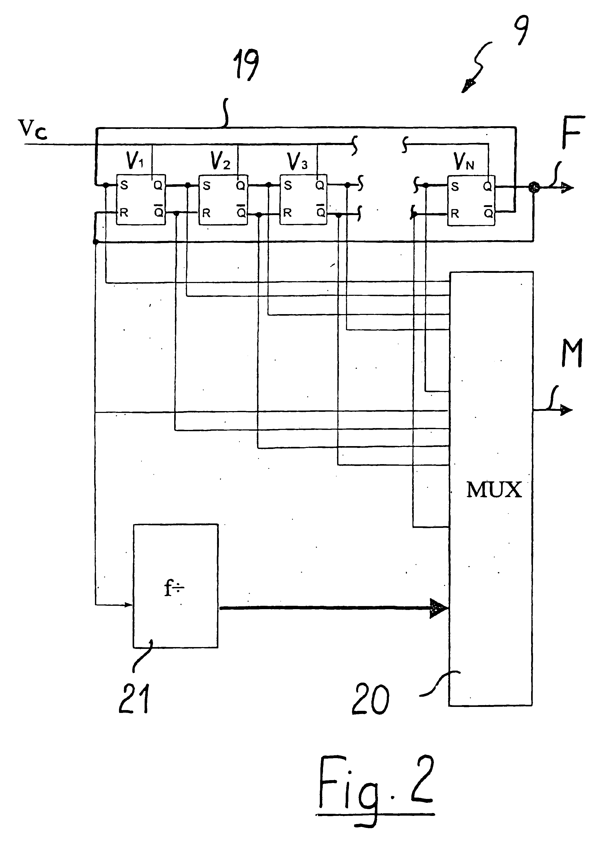
In a method and a device for carrying frequency synthesis, in particular in a distance measuring device based on the principle of evaluating the change over time in the phase of an electromagnetic radiation emitted by a radiation source and remitted by an object aimed at, a frequency, which is preferably furnished by a quartz oscillator, is regulated in a ring oscillator with N delay elements (V1, V2, V3, . . . , VN) to a desired first high frequency (F), which is used as a mixer frequency or as a modulation frequency. The signals at the N delay elements (V1, V2, V3, . . . , VN) are delivered to a multiplexer, which is switched over with a cadence that is equivalent to 2*N times the frequency of the low-frequency measurement signal to be evaluated to produce a modulation frequency or mixer frequency.

Description

BACKGROUND1. FieldThe invention relates to a method and a device for carrying out frequency synthesis in a distance measuring device. The invention also relates to a distance measuring device.2. Background InformationIn construction surveying or in interior construction, for instance for three-dimensional measurement of rooms, electronic distance measuring devices are often used. They have a distance measurement range of several tens of meters and are often embodied as handheld devices. Other areas of application for distance measuring devices are geodetic and industrial surveying or measurement. The fundamental principle of distance measurement with the known devices is based on the evaluation of a change over time in a parameter of the electromagnetic radiation emitted by the device and remitted by an object aimed at. To that end, the distance measuring device is equipped with an emitter for emitting an intensity-modulated radiation. In handheld devices, this is predominantly an o...

Claims


Application Information

Patent Timeline
Patent Type & Authority Patents(United States)
IPC IPC(8): G01S17/36G01S17/00G01S7/48G01S7/491
CPCG01S17/36G01S7/4911G01S7/4915
Inventor GIGER, KURT
Owner LEICA GEOSYSTEMS AG
Learn More