Sub-harmonic mixer

a sub-harmonic mixer and mixer technology, applied in the field of mixers, can solve the problems of large volume, high cost, and inability to provide adequate output power at millimeter wave frequencies

Active Publication Date: 2005-03-01
COMS IP HLDG LLC
View PDF5 Cites 16 Cited by
  • Summary
  • Abstract
  • Description
  • Claims
  • Application Information

AI Technical Summary

Benefits of technology

Advantageously, this arrangement provides a sub-harmonic mixer in which a local oscillator signal voltage across the gate-source of one FET and an anti-phase local oscillator signal voltage across the gate-source of the other FET are provided by driving a single gate and maintaining the potential of the other gate at a substantially constant value relative to that of the driven gate, thereby removing the need for a hybrid coupler which is used in conventional gate-fed sub-harmonic mixers to provide anti-phase local oscillator signals to the gates of the FET pair. Advantageously, removal of the hybrid coupler which occupies a substantial area of an MMIC mixer circuit simplifies the fabrication process and allows the area required for the mixer to be significantly reduced, thereby reducing costs. Furthermore, this arrangement allows the local oscillator to be coupled directly to one of the gates of the field effect transistors so that local oscillator power can be coupled more efficiently into the sub-harmonic mixer than previously possible due to the insertion loss associated with the use of a hybrid coupler in conventional mixers.
Embodiments of the present invention may further comprise DC coupling means for coupling the drains of each of the first and second field effect transistors to DC ground. Preferably, embodiments of the present invention further comprise filter means for preventing the input signal and the output signal passing through the DC coupling means.

Problems solved by technology

This proximity of the local oscillator frequency to the RF frequency can lead to undesirable LO frequency radiation, and also isolation problems between the RF and LO mixer ports.
Another drawback of using fundamental mixers in microwave frequency applications is that the local oscillators required to provide adequate output power at millimeter wave frequencies tend to be relatively bulky and expensive.

Method used


Image

  • Sub-harmonic mixer
  • Sub-harmonic mixer
  • Sub-harmonic mixer

Examples


Embodiment Construction

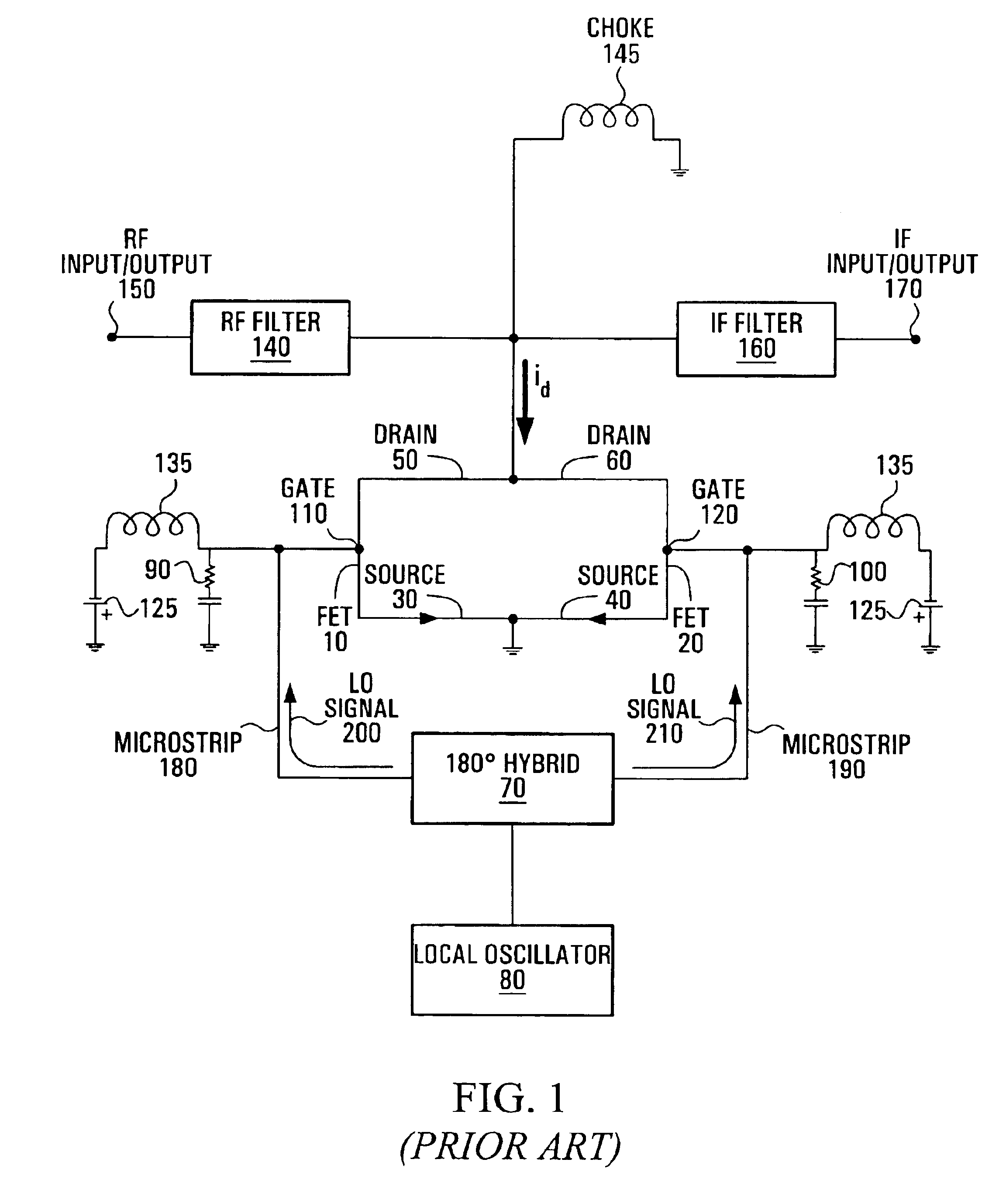
Referring to FIG. 1, shown is a circuit diagram of a conventional gate-driven sub-harmonic mixer. A first FET (Field Effect Transistor) 10 and a second FET 20 each have a respective source 30, 40, a respective drain 50, 60 and a respective gate 110, 120. The drains 50, 60 are connected together, and the sources 30, 40 are connected together, and also to ground. A 180° hybrid 70 is connected to the gates 110, 120 of the FETs 10, 20, through a respective conducting microstrip 180, 190, and a local oscillator 80 is connected to the 180° hybrid 70. An ac grounded resistor 90, 100 is also connected to a respective gate 110, 120 of the FETs 10, 20. A choke 145 connects the drains 50, 60 of the FETs 10, 20 to DC ground. An RF filter 140 is connected between an RF input / output 150 and the drains 50, 60, and an IF (intermediate frequency) filter 160 is connected between an IF input / output 170 and the drains 50, 60.

A signal of frequency, f0, is generated by the local oscillator 80 and split b...


PUM


Abstract

A sub-harmonic mixer comprises two field effect transistors in which the sources of the transistors are connected together and the drains of the transistors are connected together. The mixer includes signal generating means for generating a local oscillator (LO) signal coupled to the gate of one of the FETs. Circuit means is provided for maintaining the potential of the gate of the other FET at a substantially constant value relative to the local oscillator signal applied to the gate of the driven FET, and the FET's are arranged to permit the local oscillator signal applied to gate of the driven FET to drive a voltage across the gate-source of both FET's. An input and output port is coupled to the drains for receiving input signals for the mixer and outputting output signals from the mixer.

Description

FIELD OF THE INVENTIONThe present invention relates to mixers for wireless receivers and transmitters, and in particular to sub-harmonic mixers.BACKGROUND OF THE INVENTIONReceiver circuits for millimeter wave wireless communication systems typically include a low noise amplifier (LNA) and a down-converter for converting the received, high frequency signal to a lower, intermediate frequency (IF) signal, from which the baseband signal is subsequently extracted. Monolithic microwave integrated circuit (MMIC) fabrication technology enables the low noise amplifier and down-converter mixer circuits to be formed on a single integrated circuit chip, in order to improve performance, simplify production and reduce costs. For relatively low microwave carrier frequencies, the down-converter may employ a fundamental mixer, in which the same frequency generated by the local oscillator (LO) is mixed with the received RF signal to generate the intermediate frequency components. At low microwave fre...

Claims


Application Information

Patent Timeline
Patent Type & Authority Patents(United States)
IPC IPC(8): G06G7/14G06G7/12G06G7/00H03D7/12
CPCH03D7/125
Inventor ROMANO, ANTONIO
Owner COMS IP HLDG LLC
Why Eureka
Try Eureka