U-tube diffusion flame burner assembly having unique flame stabilization

Inactive Publication Date: 2005-03-29
HAUKE MFG
View PDF42 Cites 34 Cited by
  • Summary
  • Abstract
  • Description
  • Claims
  • Application Information

AI Technical Summary

Benefits of technology

An advantage of the present invention is that it provides a more efficient combustion of the fuel as the secondary air is heated to provide a recuperative effect. Thus, the air from the secondary air tube is provided to the combustor at a higher temperature than if there were no recuperative effect. The walls of the secondary air tube act as a heat exchanger to more efficiently transfer heat to the secondary air and heat it to higher temperatures than heretofore possible.
Another advantage of the present invention is that it provides a more stable flame. The air is swirled in such a manner as to stabilize the flame within the recirculation zone, allowing combustion to continue even under transient conditions of secondary air flow, without concern about flame extinguishment as a result of the formation of a plurality of stationary vortices. The design of the unit does not produce undesirable acoustic effects normally associated with diffusion flame gas

Problems solved by technology

If the flame front is not anchored at a fixed start location, undesirable acoustics will develop in the tube.
While the burner set forth in the '143 patent is particularly effective in permitting a change from one fuel to another, it is complex and expensive, but can introduce undesirable acoustics.
A difficulty that can be encountered by burners that rely on swirling air to improve mixing is that the secondary air is introduced and swirled at a first end, but exits the secondary tube at a second end.
The swirling air modifies the acoustics of the burner, producing undesirable acoustics that are very unpleasant, and potentially damaging noise, to anyone in the vicinity.
Additionally, with changing conditions as the air flow is modified, th

Method used


Image

  • U-tube diffusion flame burner assembly having unique flame stabilization
  • U-tube diffusion flame burner assembly having unique flame stabilization
  • U-tube diffusion flame burner assembly having unique flame stabilization

Examples


Example

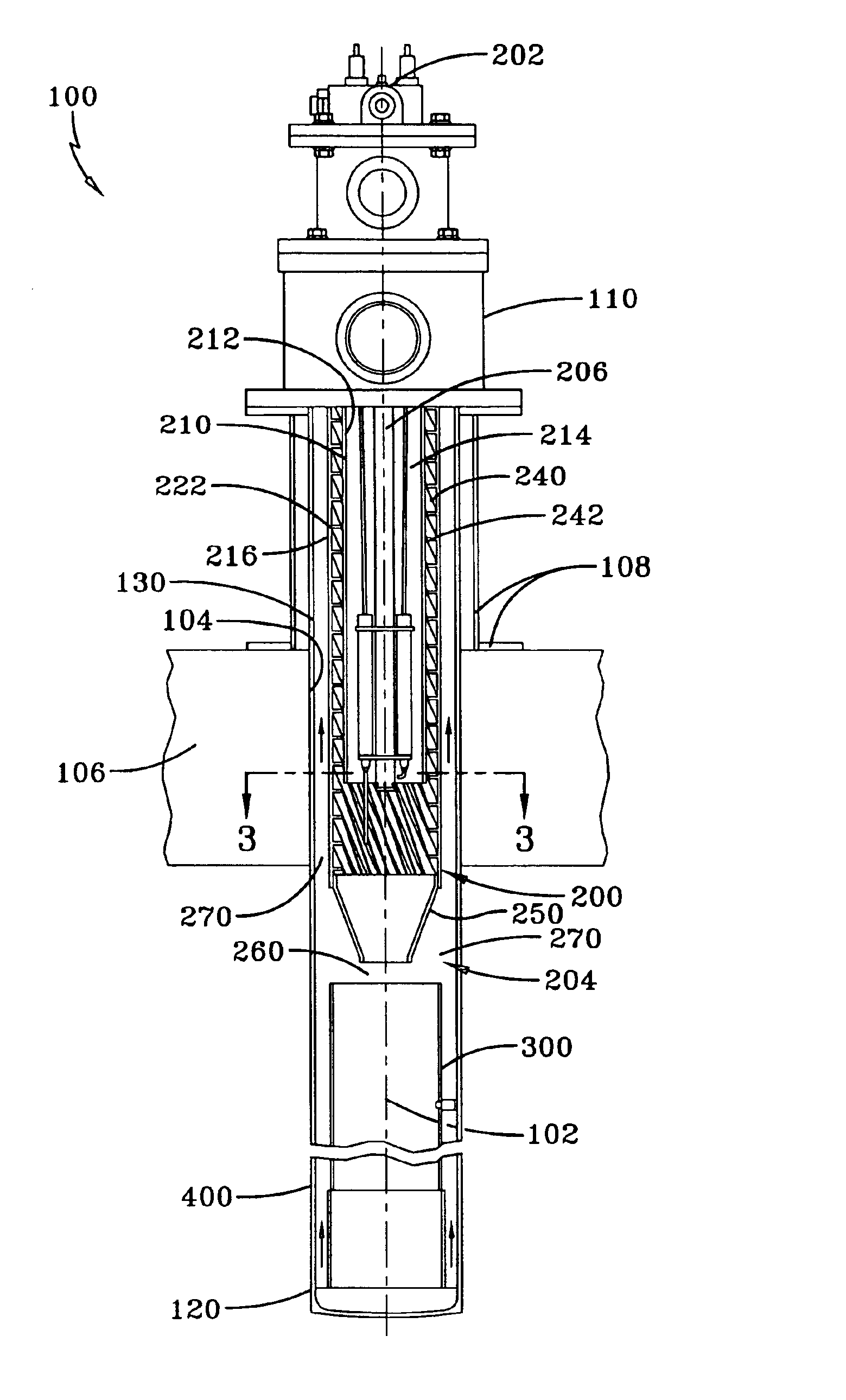
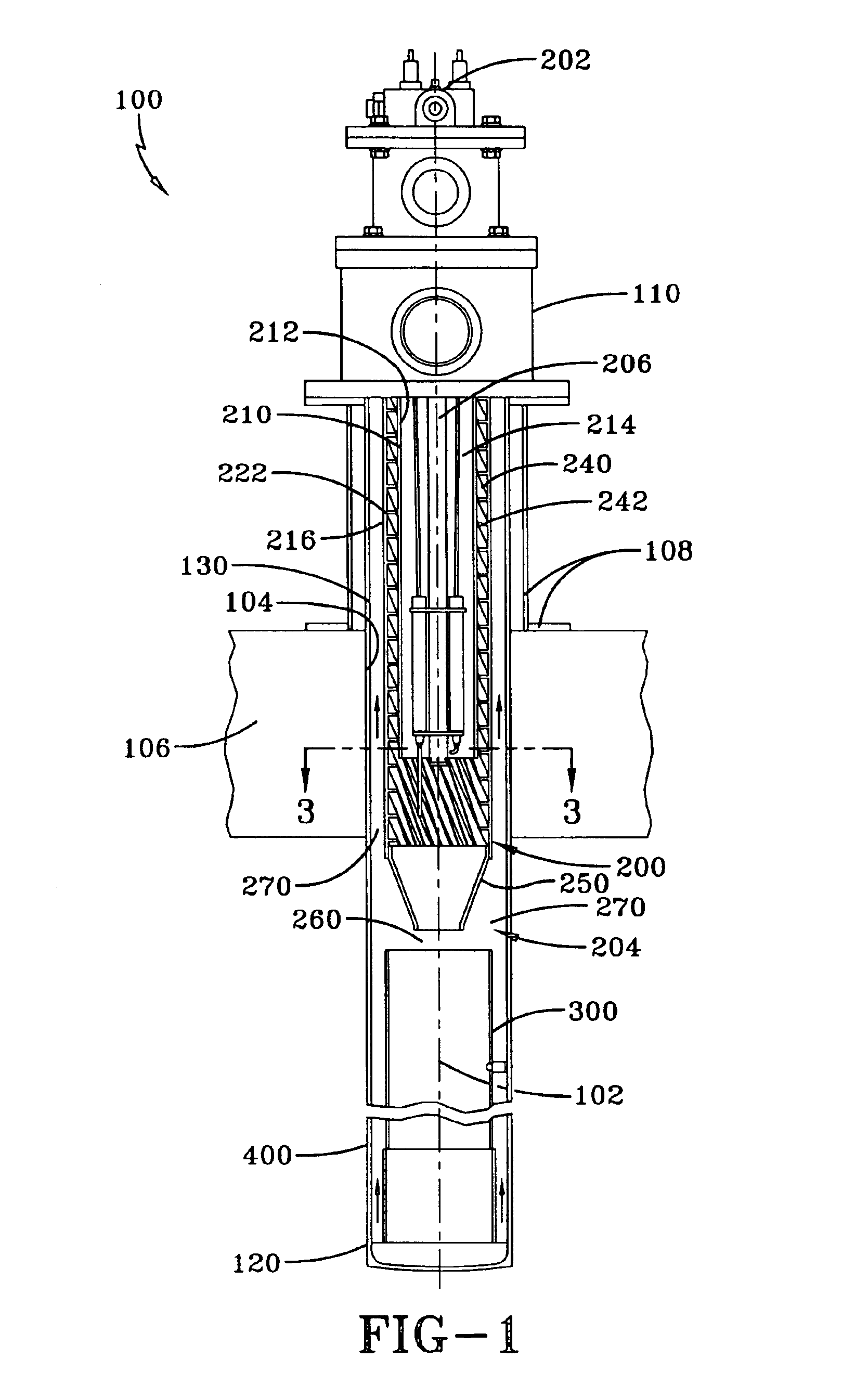
FIG. 1 depicts the present invention included as a flame holder and combustor in a self-recuperative single-ended radiant tube burner. Self-recuperative burners require an effective built-in heat exchange to transfer heat which is otherwise lost as waste form the exhaust gas to the incoming combustion air. Ideally, the flame retaining mechanism and the heat exchanger should be as simple in construction as possible while also being resistant to heat and flames. Referring now to FIG. 1, the self-recuperative, single-ended radiant tube burner 100 of the present invention includes a central axis 102 and is comprised of a flame holder 200 and an inner flame tube 300. The self-recuperative, single ended radiant tube burner 100 has a first end 110, a second end 120 and an exhaust housing 130 that extends between the first end 110 and the second end 120. Housing 130 extends through an aperture 104 in a furnace wall 106. The portion of housing 130 extending through furnace wall 106 is referr...


PUM


Abstract

A U-tube diffusion flame burner assembly having improved flame stabilization with no undesirable acoustic effects. The burners are axial units comprised of flame holders and combustors. The flame holders includes secondary air tubes to support the flow of secondary air that have helical walls forming helical passageways along at least a portion of its inner diameter to impart a swirl to the secondary air. The helical passageways impart a swirl to the secondary air exiting the passageways while simultaneously acting as a heat exchanger to heat primary air. The flame holders includes fuel tubes having first ends connected to a fuel supply and second flame ends. A plurality of radially oriented apertures are located at the second flame ends to distribute fuel in a radial direction. Primary air tube surrounds at least the flame ends of the fuel tubes and extend axially from first air supply ends to second flame ends. Air is diverted from air supply ends of the flame burners into primary air tubes through radial apertures located at the first air supply ends of the primary air tubes. Secondary air tubes surround the primary air tubes extending from first air supply ends to second ends opposite the air supply, the secondary air tubes having inner diameters larger than the outer diameters of the primary air tubes. The secondary air tubes extend for a preselected distance beyond the second flame ends of the primary air tubes and are coupled to axially-oriented conical-shaped reducers. Flame at high velocity exits the restricted end of the reducers.

Description

FIELD OF THE INVENTIONThe present invention is generally directed to a gas burners using a diffusion flame with a unique flame stabilization method and specifically to a burner system for a U-tube type burner using self-recuperative radiant tube burners.BACKGROUND OF THE INVENTIONDiffusion flame (nozzle mixing) gas burners are used in various industrial kilns and furnaces. There are various types of units used in such furnaces, including but not limited to self-recuperative single-ended radiant tube burners. These burners have flame contained within the tube, which tube then radiates heat into the furnace. The units are designed so that no products of combustion enter the work processing chamber of the furnace. Substantially all of the products of combustion are exhausted rearward through the burner outside of the work processing chamber of the furnace and in a direction substantially opposite the flame direction. These exhaust gases preheat the incoming combustion air by extracting...

Claims


Application Information

Patent Timeline
IPC IPC(8): F23D14/70F23D14/46F23D14/24F23D14/00F23C3/00F23C7/00F23C7/06
CPCF23C3/002F23C7/002F23C7/06F23D14/66F23D14/70F23D14/24F23D2210/00F23D2203/005Y02E20/34
Inventor MOORE, EDWARD E.MARINO, JOHN A.
Owner HAUKE MFG
Why Eureka
Try Eureka