Stand alone plasma vacuum pump

a vacuum pump and plasma technology, applied in mechanical equipment, machines/engines, positive displacement liquid engines, etc., can solve the problems of not being developed, effective systems for achieving high, and existing vacuum pumping technology can only provide limited gas throughput, etc., to achieve the effect of promoting plasma flow

Inactive Publication Date: 2005-03-29
TOKYO ELECTRON LTD +1
View PDF28 Cites 5 Cited by
  • Summary
  • Abstract
  • Description
  • Claims
  • Application Information

AI Technical Summary

Benefits of technology

According to the invention, a stand-alone plasma vacuum pump for pumping gas from a low-pressure inlet to high-pressure outlet combines an electron cyclotron resonance effect with a specially shaped permanent magnet field to propel ions from the inlet to the outlet. The plasma vacuum pump includes a housing enclosing a pumping region located between the inlet and the outlet, a plurality of permanent magnet assemblies providing magnetic fields that extend in the pumping region between the inlet and the outlet, the magnetic fields providing at least one magnetic flux channel for guiding and confining a plasma, and a source of microwave power coupled into the flux channel to heat plasma electrons, ionize the gas, and create forces that propel plasma ions in a direction from the inlet toward the outlet. The pump is further constructed to promote the flow of plasma and electrically neutral gas molecules toward the outlet while impeding flow of neutral gas molecules in the direction from the outlet toward the inlet.

Problems solved by technology

However, existing vacuum pumping technology can provide only limited throughput of gas in this pressure range.
Robust, cost-effective systems for achieving high-speed pumping in the pressure range from 1-10 milliTorr have not been developed to date.
Furthermore, many gases involved in industrial processing of, for example, VLSI systems are toxic or hazardous and must be isolated and controlled with great care.
The resulting limit on maximum gas throughput that can be achieved with turbomolecular pumps is a drawback in the plasma processing industry where substantial throughputs of reactant gases are needed to prevent the buildup of reaction products to concentrations that would be deleterious to the process.
Further, high-speed turbomolecular pumps are necessarily complex and expensive devices, in which large angular momentum is stored.
Moreover, many plasma processes yield solid and / or corrosive byproducts that can be potentially damaging to these pumps.
At present the capability of turbomolecular pumps is limited to 5500 liters per second; although the use of the largest available turbomolecular pumps is further limited by the cost of the large pumps and the expected lack of reliability of a pump this large.
Thus, the cost per unit pumping speed for the larger pumps is 50% greater than for the smaller pumps.
Extension to 300 mm wafers significantly exacerbates the problem of providing adequate pumping speed.
This leaves the 300 mm systems with pumping options that are grossly inadequate.
The problem of gas handling in 300 mm systems is complicated even further by the fact that it is the pumping speed at the wafer (substrate) that is most important.
In most processes of commercial interest, however, the flow is characterized as transition flow and the computer models are less reliable in predicting performance.
A similar problem occurs with any barely volatile species that may result from the process itself, for example, multiple carbon species that are polymerized either by the electrons or photons of the plasma.
This last technical difficulty is exacerbated by the plasma's ability to shield its interior from low-frequency external electric fields, together with the complex atomic and molecular processes that become important in the pressure range of interest.
It can not be used as a stand-alone vacuum pump.

Method used


Image

  • Stand alone plasma vacuum pump
  • Stand alone plasma vacuum pump
  • Stand alone plasma vacuum pump

Examples


Embodiment Construction

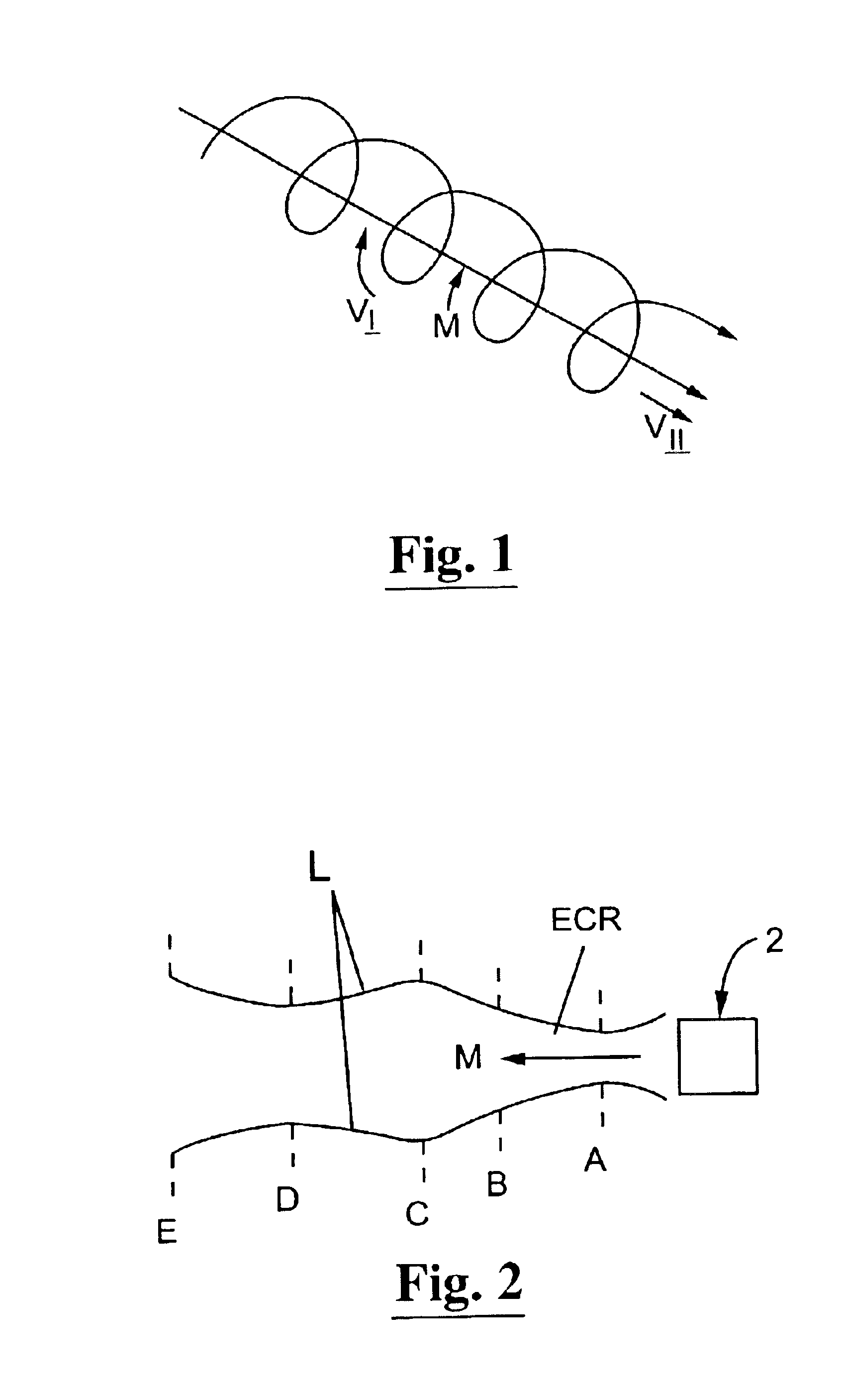
FIG. 1 illustrates the helical trajectory of an electron moving in a static magnetic field having lines of force which extend in the general direction of arrow M. As is well known in the art and described more fully in, for example, Plasmas and Controlled Fusion, by David J. Rose and Melville Clark, Jr., John Wiley and Sons, New York (1961) Chapter 10, the helical trajectory illustrated in FIG. 1 can be regarded as resulting from the superposition of a transverse rotational motion (“gyration”) around the magnetic lines of force and a lineal motion along the magnetic line of force. The angular frequency of the gyration (the “electron gyrofrequency”), Ωe, is proportional to the magnitude of the magnetic field strength, B=|B|:

Ωe=2πfe=eB / m

Here e and m are the electric charge and mass of the electron, respectively. In a magnetic field of 875 Gauss, for example, the electron gyrofrequency, fe, equals 2.45 GHz, the frequency of the microwave power used in many commercial applications.

If mi...


PUM


Abstract

A stand-alone plasma vacuum pump for pumping gas from a low-pressure inlet to a high-pressure outlet, composed of: a housing enclosing one or more pumping regions located between the inlet and the outlet; a plurality of permanent magnet assemblies providing magnetic fields that extend in the pumping region between the inlet and the outlet, the magnetic field forming magnetic flux channels for guiding and confining plasmas; elements disposed for coupling microwave power into the flux channels to heat electrons, ionize gas, and accelerate plasma ions in a direction from the inlet to the outlet; elements disposed for creating an electric in the magnetic flux channels to accelerate ions in the flux channels toward the outlet by momentum transfer; and a differential conductance baffle proximate to the outlet for promoting flow of plasma ions and neutral atoms to the outlet.

Description

BACKGROUND OF THE INVENTIONThe present invention relates to industrial and other processes in which large volumes of gases must be pumped at pressures as low as 1-10 milliTorr. Industrial processes in this category include, for example, various types of plasma processing, such as plasma enhanced chemical vapor deposition, plasma mediated etching of surfaces, and other types of surface modification processes.In many such processes employing plasmas, it is generally considered by those skilled in the art to be advantageous to generate the processing plasmas in suitable mixtures of gases maintained at pressures as low as 1-10 milliTorr. The purity and composition of the gas can best be controlled if the flow rate of fresh gas into the processing chamber is high relative to the processing rate. However, existing vacuum pumping technology can provide only limited throughput of gas in this pressure range.The pumping speed of widely used turbomolecular vacuum pumps, for example, generally ...

Claims


Application Information

Patent Timeline
Patent Type & Authority Patents(United States)
IPC IPC(8): H01J41/00H01J41/20
CPCH01J41/20
Inventor DANDL, RAPHAEL A.QUON, BILL H.
Owner TOKYO ELECTRON LTD
Why Eureka
Try Eureka