
Composite construction and manufacturing method thereof

a technology of composite materials and manufacturing methods, applied in the field of composite materials, can solve the problems of large residual stress between the core material and the shell layer, formation of voids, and the need to decompose and volatilize a large amount of organic binder, and achieve excellent strength, hardness and toughness

Inactive Publication Date: 2005-04-12
KYOCERA CORP
View PDF4 Cites 10 Cited by
  • Summary
  • Abstract
  • Description
  • Claims
  • Application Information

AI Technical Summary

Benefits of technology

[0006]It is a main object of the present invention to provide a composite construction exhibiting excellent strength, hardness and toughness even when molding and sintering are performed by adding in particular a large amount of organic binder, as well as a method of manufacturing the same.
[0007]It is another object of the present invention to provide a composite construction capable of efficiently performing binder burnout treatment even when molding and sintering are performed by adding a large amount of organic binder, as well as a method of manufacturing the same.
[0008]The present inventors considered the above problem and found the followings. In the case of reducing the amount of excess residual free carbon remaining in a core material, it is possible to reduce the amount of shrinkage occurred when sintering the core material and reduce the residual stress between the core material and shell layer. This eliminates delamination and residual stress occurred between the core material and shell layer, thereby providing a composite construction excellent in hardness, toughness and strength.
[0010]A second method for reducing the amount of carbon remaining in a core material is that an oxide powder that changes to a hard particle or ceramic particle of carbide, nitride or carbonitride is added to the raw material of the core material, and during the time of sintering or before sintering, the oxide powder is subjected to carbonization or subjected to carbonization and nitriding in order to release oxygen, and then allowed to react with the residual free carbon remaining as a residue of an organic binder. A third method for reducing the amount of carbon remaining in a core material is that an iron family metal oxide powder is added to the raw material of the core material, and during the time of sintering or before sintering, the iron family metal oxide powder is subjected to reduction in order to release oxygen, and then allowed to react with the residual free carbon remaining as a residue of an organic binder. A composite construction excellent in hardness and toughness and also excellent in strength is obtainable because the oxide powder can be changed to a carbide, nitride, or carbonitride, each having a higher hardness.

Problems solved by technology

Therefore, during the time of sintering, a large amount of the organic binder are decomposed and volatilized, thereby forming voids.
As the result, in the composite construction obtained by sintering, a large residual stress occurs between the core material and shell layer.
Further, with the above method, it is necessary to decompose and volatilize a large amount of the organic binder.
In practice, binder burnout treatment has a limitation.
Particularly, when there is a large amount of the organic binder remaining without being decomposed and volatilized, i.e., residual free carbon, in the core material located at the inside of the composite construction, the core material suffers from poor sintering and its sintered density does not increase, thus deteriorating the strength of the composite construction.

Method used


Image

  • Composite construction and manufacturing method thereof
  • Composite construction and manufacturing method thereof
  • Composite construction and manufacturing method thereof

Examples


example 1

[0081]To a mixture of 75% by weight of WC powder having an average particle diameter of 1.5 μm, 10% by weight of Co powder having an average particle diameter of 1 μm, 5% by weight of TiC powder having an average particle diameter of 2 μm, and 10% by weight of metal W powder having an average particle diameter of 1 μm, cellulose and polystyrene glycol as organic binder, and polyvinyl alcohol as solvent were added in the total amount of 100 parts by volume. This mixture was then kneaded and extruded in a cylindrical shape, thereby obtaining a core material molding.

[0082]On the other hand, to a mixture of 50% by weight of TiCN powder having an average particle diameter of 1.5 μm, 10% by weight of TiC powder having an average particle diameter of 1.5 μm, 7% by weight of Co powder having an, average particle diameter of 1 μm, 20% by weight of WC powder having an average particle diameter of 1.5 μm, 7% by weight of Mo2C powder having an average particle diameter of 2 μm, and 6% by weight...

example 2

[0089]A composite construction was manufactured in the same manner as Example 1, except that the material for shell layer in Example 1 was changed to a mixture of 80% by weight of WC powder having an average particle diameter of 0.2 μm, 8% by weight of Co powder having an average particle diameter of 0.5 μm, 0.3% by weight of VC powder having an average particle diameter of 0.8 μm, 0.7% by weight of Cr3C2 powder having an average particle diameter of 0.8 μm, and 11% by weight of metal W powder having an average particle diameter of 0.3 μm. The same evaluation was conducted and the following results were obtained. The residual free carbon amount Cin in the core material was 0.38% by weight, the residual free carbon amount Cout in the shell layer was 0.30% by weight, and the ratio Cin / Cout was 1.3. By measuring the residual stress in the interface between the core material and shell layer by X-ray diffraction, it was found that tensile stress of 43 MPa was present. The three-point ben...

example 3

[0090]A composite construction was manufactured in the same manner as Example 1, except that (i) the material for core material in Example 1 was changed to a mixture of 50% by weight of silicon carbide powder having an average particle diameter of 2 μm, 23% by weight of aluminum nitride powder having an average particle diameter of 2 μm, 17% by weight of alumina powder, and 10% by weight of metal silicon powder, (ii) the material for shell layer in Example 1 was changed to a mixture of 97% by weight of Si3N4 powder having an average particle diameter of 2 μm, 2% by weight of Y2O3 powder having an average particle diameter of 1.5 μm, and 1% by weight of Al2O3 powder having an average particle diameter of 1 μm, and (iii) the temperature at which the construction was sintered was changed to 1900° C. The same evaluation was conducted and the following results were obtained. The residual free carbon amount Cin in the core material was 0.20% by weight, the residual free carbon amount Cout...


PUM

PropertyMeasurementUnit
tensile stressaaaaaaaaaa
particle diameteraaaaaaaaaa

Abstract

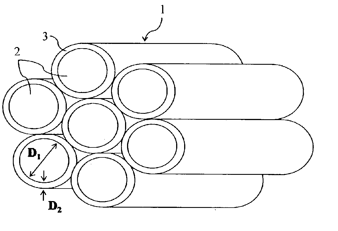
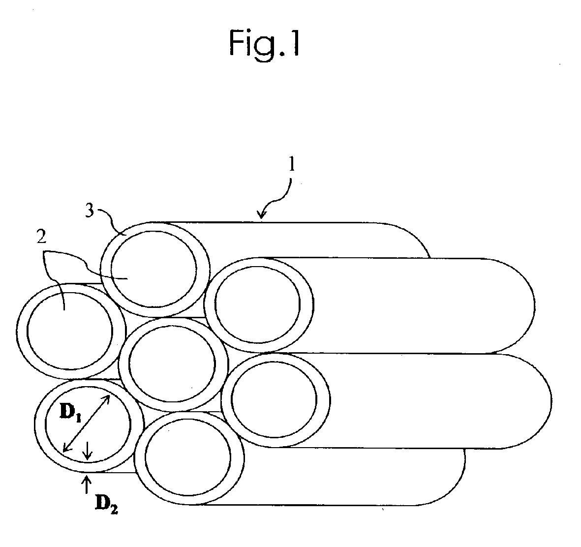
A composite construction 1 is obtained by coating the outer periphery of a core material 2 with a shell layer 3. The core material 2 is composed of a first sintered body that is obtained by bonding, with a binder metal, a first hard particle composed of one or more of carbides, nitrides and carbonitrides of metals of Groups 4a, 5a and 6a of the Periodic Table, or a first ceramics obtained by bonding, with a sintering additive, a first ceramic particle composed of at least one of oxides, carbides, nitrides and carbonitrides selected from the group consisting of metals of Groups 4a, 5a and 6a of the Periodic Table, Al, Si and Zn. The shell layer 3 is composed of a second hard sintered body or second ceramics having a different composition from the first hard sintered body. The ratio of the residual free carbon amount Cin in the core material 2 to the residual free carbon amount Cout in the shell layer 3, Cin / Cout, is 0.5 to 2. This prevents shrinkage during the time of sintering and also prevents the strength of the composite construction from lowering due to poor sintering.

Description

FIELD OF THE INVENTION[0002]The present invention relates to a composite construction obtained by coating the outer periphery of a core material with a shell layer having a different composition from the core material, as well as a method of manufacturing the same.BACKGROUND OF THE INVENTION[0003]Conventionally, there has been studied a technique of improving the toughness of a construction in addition to its hardness and strength by coating the outer periphery of a continuous core material, such as fabrics, with other material. For example, U.S. Pat. No. 5,645,781 describes that a composite construction excellent in toughness indicating non-brittle fracture characteristic is obtainable by stretching by co-extrusion a laminated molding in which the outer periphery of a cylindrical core material molding composed of a first ceramic powder containing a large amount of organic binder (thermoplastic polymer) is surrounded by a shell layer molding consisting of a second ceramic powder dif...

Claims


Application Information

Patent Timeline
Patent Type & Authority Patents(United States)
IPC IPC(8): B22F7/06B29C47/02C04B35/117C04B35/111C04B35/119C04B37/00C22C47/14C22C1/05C22C49/00C22C47/00B29C48/05B29C48/154
CPCB22F7/062B29C47/0014B29C47/025B32B18/00C04B35/117C04B35/119C04B35/5626C04B35/565C04B35/58021C04B35/584C04B37/001C22C1/053C22C47/14C22C49/00Y10T428/24942B32B2315/02C04B2235/3206C04B2235/3217C04B2235/3225C04B2235/3232C04B2235/3277C04B2235/3418C04B2235/3826C04B2235/3839C04B2235/3843C04B2235/3847C04B2235/3865C04B2235/3873C04B2235/3886C04B2235/404C04B2235/405C04B2235/428C04B2235/5436C04B2235/5445C04B2235/6021C04B2235/652C04B2235/6581C04B2235/668C04B2235/721C04B2235/728C04B2235/80C04B2235/94C04B2235/96C04B2237/343C04B2237/348C04B2237/36C04B2237/361C04B2237/363C04B2237/365C04B2237/368C04B2237/704B22F2999/00Y10T428/2918B22F3/20B29C48/05B29C48/154Y10T428/249967
Inventor FUJIOKA, HIROMISHIBATA, DAISUKENAKAOKA, TATSUYUKI
Owner KYOCERA CORP
Learn More