Deposition monitoring system

a monitoring system and technology of deposition, applied in the direction of cathode-ray oscilloscope, survey, borehole/well accessories, etc., can solve the problems of inability to monitor the tubing of a producing hydrocarbon well can be a major and costly problem, and the near wellbore region of organic and inorganic deposits, etc., to achieve the effect of increasing the thickness of the deposi

Inactive Publication Date: 2005-04-19
SCHLUMBERGER TECH CORP
View PDF40 Cites 126 Cited by
  • Summary
  • Abstract
  • Description
  • Claims
  • Application Information

AI Technical Summary

Benefits of technology

[0024]The growth of wellbore deposits is monitored by the decrease in the resonant frequency of the transducer with increasing thickness of deposit. The resonant frequency is conveniently determined from the real part of the admittance spectrum of the transducer. The horn amplifies the effect of the scale deposit on the measured admittance of the transducer.

Problems solved by technology

The formation of both organic and inorganic deposits in the near wellbore region of producing formations and on the tubing of a producing hydrocarbon well can be a major and costly problem.
The deposits can seriously impede the productivity of wells by reducing the near wellbore permeability of producing formations and progressively restrict the diameter of the tubing.
In extreme cases the production tubing must be removed and replaced, although the presence of radioactive scale (due to the presence of radium salts) can make scale disposal an environmental issue.
The precipitates can be removed with solvent washes, although the disposal of the solvent after cleaning represents an increasing environmental problem.
However, thermodynamic models are essentially equilibrium models and they cannot predict any details of the precipitation process such as the location of precipitation, the rate of precipitation or the degree of supersaturation that the fluid can tolerate.
For example, measurements made using ultrasound below a frequency of 3 MHz gave poor sensitivity to scale thickness and beam spreading was observed to be a problem.
However, the use of acoustic energy to clean the organic precipitates from the acoustic sensor was not disclosed or suggested.
Note that this method of monitoring scale formation is not an in situ method and does not measure the spontaneous formation of scale under downhole conditions of temperature, pressure, composition and flow.
In addition, the resonator was not able to clean the scale from its sensing surface.
However, no details were given of the power or frequency of the sound used for wellbore cleaning.
The vibrations were generated in the device by an orbiting mass on an unbalanced rotor, which, in turn, produced a whirling vibratory pressure of large amplitude in the fluid in the annulus.
Using the same ultrasonic transducers, it was demonstrated that polymer-induced formation damage was considerably more difficult to remove than the damage caused by clay fines.
In conclusion, there appears to be no prior art that teaches or suggests either an acoustic scale sensor or an acoustic cleaning device located permanently or quasi-permanently in a well producing hydrocarbons.
Additionally, there appears to be no prior art that teaches or suggests an on-line deposits monitoring and cleaning device located on the surface facilities of a producing oil well using an ultrasonic transducer operating in its longitudinal mode and coupled to the produced fluids using a coupling material, such as an acoustic horn, to which the deposits adhere.

Method used


Image

  • Deposition monitoring system
  • Deposition monitoring system
  • Deposition monitoring system

Examples


Embodiment Construction

(I) ACOUSTIC SCALE / DEPOSITS SENSOR

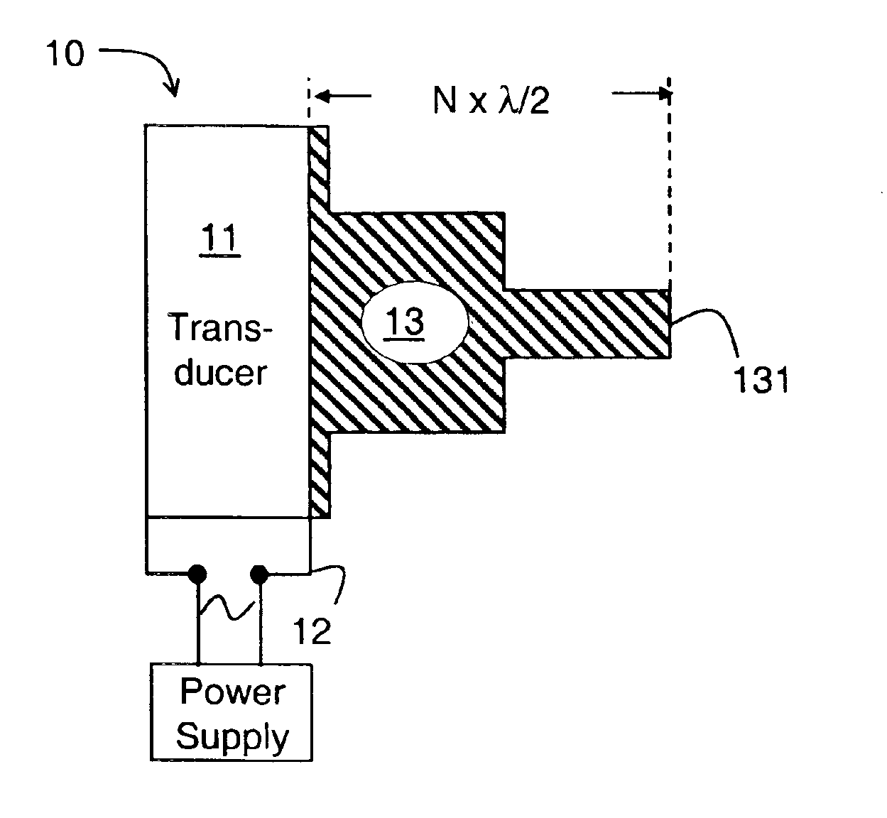
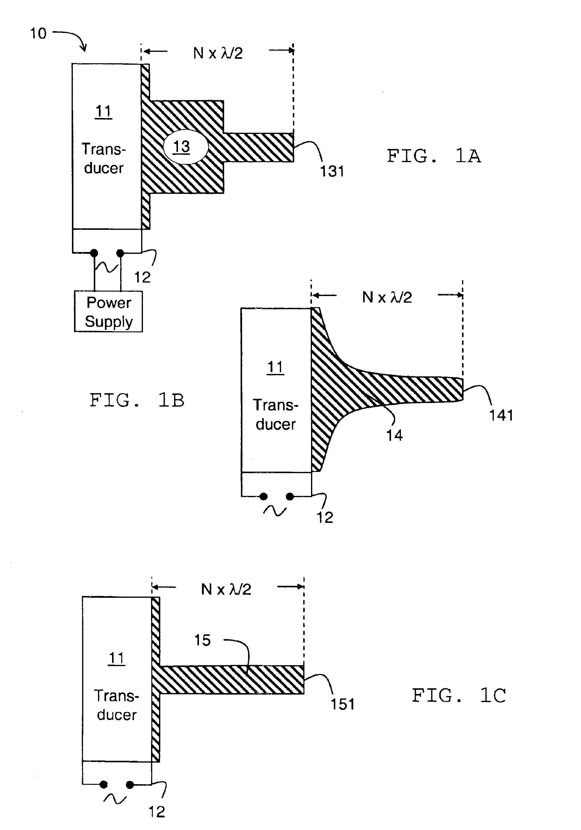
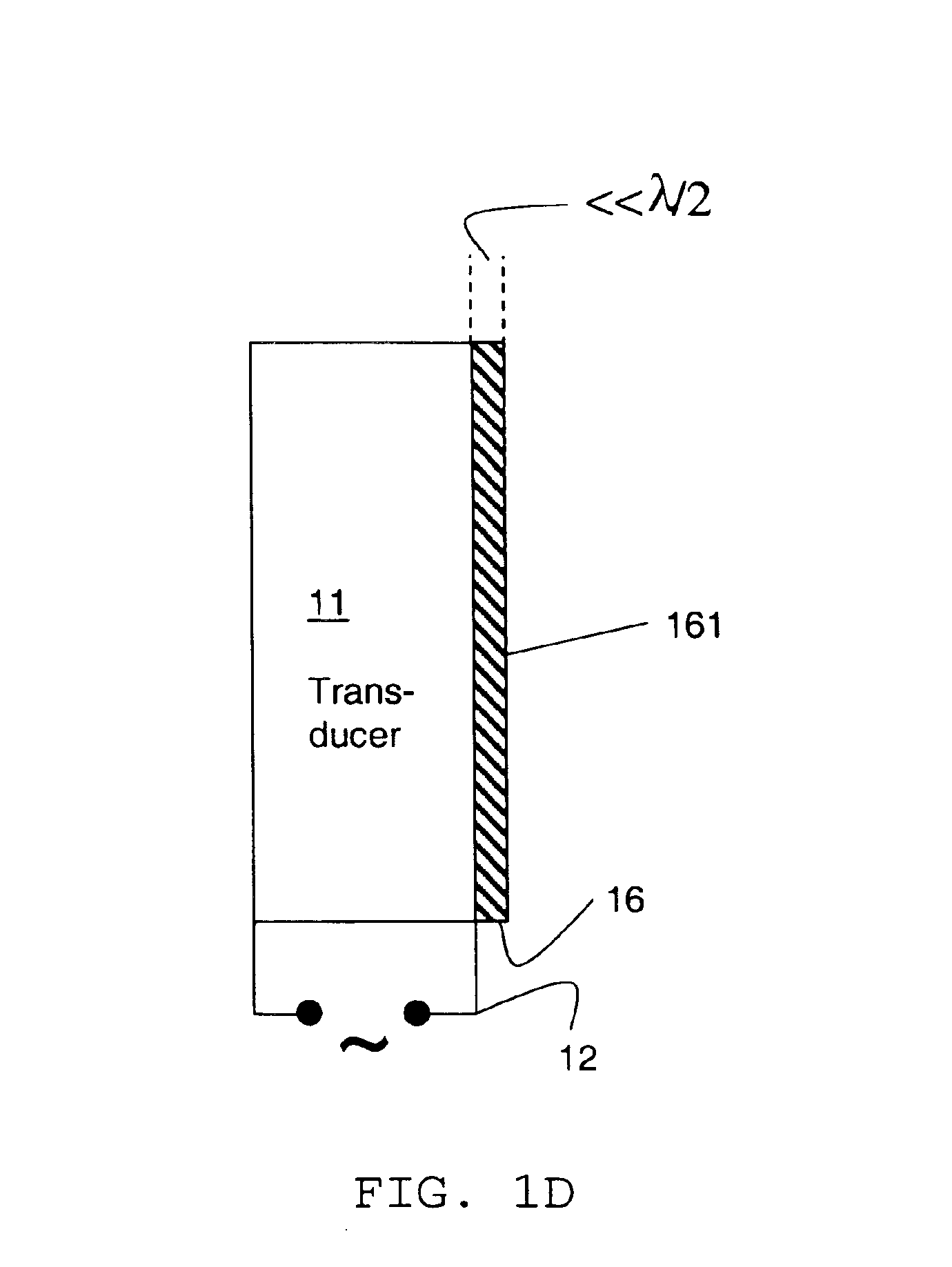
[0045]The scale (or deposits) sensor consists of an ultrasonic piezoelectric transducer operating in a longitudinal mode coupled to a suitable metal horn. The resulting ultrasonic device is characterised by a sharp resonant frequency, which can be conveniently determined by the measurement of the admittance (or impedance) spectrum of the device. The resonance frequency of the appropriate longitudinal mode is sensitive to any solid deposit that forms on the tip of the horn and the magnitude of the frequency shift is a measure of the mass loading. These ultrasonic transducers typically operate in the frequency range 10-100 kHz and can deliver high levels of acoustic power, typically in the range 1-500 W, when driven by a high input alternating voltage at its resonant frequency.

[0046]FIG. 1 shows schematics of several types of acoustic horn attached to an ultrasonic transducer. The basic elements of the scale deposit sensor 10 are a transducer 11 made ...


PUM

PropertyMeasurementUnit
resonance frequencyaaaaaaaaaa

Abstract

Described is an apparatus for detecting and removing deposits from a surface exposed to wellbore fluids. The apparatus can monitor the rate of deposition and subsequently remove the deposited material. The combination of detection apparatus and removal apparatus provides an instrument with self-cleaning operation mode.

Description

[0001]This invention relates to apparatus and methods for monitoring solid deposits of material on tubing, conduits and other installations. Particularly, the invention relates to such apparatus and methods for sensing and removing material deposited by fluid from hydrocarbon wells.BACKGROUND OF THE INVENTION[0002]The formation of both organic and inorganic deposits in the near wellbore region of producing formations and on the tubing of a producing hydrocarbon well can be a major and costly problem. See, e.g. Allen, T. O. and Roberts, A. P., Production Operations, Vol. 2, 2nd edition, pp. 11-19 and 171-181, OGCI, Tulsa, Okla. (1982); Cowan, J. C and Weintritt, D. J., Water-formed Scale Deposits, Gulf Publishing Co., Houston (1976). The deposits can seriously impede the productivity of wells by reducing the near wellbore permeability of producing formations and progressively restrict the diameter of the tubing.[0003]The formation of inorganic deposits, or scale, is caused by the pre...

Claims


Application Information

Patent Timeline
Patent Type & Authority Patents(United States)
IPC IPC(8): B08B9/04B08B7/02B08B9/02E21B34/00E21B34/06E21B37/06E21B37/00E21B43/34E21B47/01E21B43/38E21B47/08E21B47/00G01N29/02G01N29/036G01N29/24G01N5/00B08B3/12
CPCB08B3/12B08B9/027E21B34/066E21B37/00E21B37/06E21B43/38E21B47/00E21B47/01E21B47/082G01N5/00G01N29/036G01N29/2456B08B7/028G01N2291/0422B08B2209/005G01N2291/0231G01N2291/02818G01N2291/02827G01N2291/02854G01N2291/02872G01N2291/0421E21B47/085E21B47/006
Inventor COUET, BENOITJONES, TIMOTHY GARETH JOHN
Owner SCHLUMBERGER TECH CORP
Why Eureka
Try Eureka