
Method of growing a thin film onto a substrate

a technology of thin film and substrate, which is applied in the direction of crystal growth process, chemical vapor deposition coating, coating, etc., can solve the problems of affecting the quality of deposited thin film, risk of microparticle formation already in the infeed, and stringent requirements on the valves employed for controlling the dosing, so as to increase reliability and reduce downtime

Inactive Publication Date: 2005-04-19
ASM INTERNATIONAL
View PDF5 Cites 30 Cited by
  • Summary
  • Abstract
  • Description
  • Claims
  • Application Information

AI Technical Summary

Benefits of technology

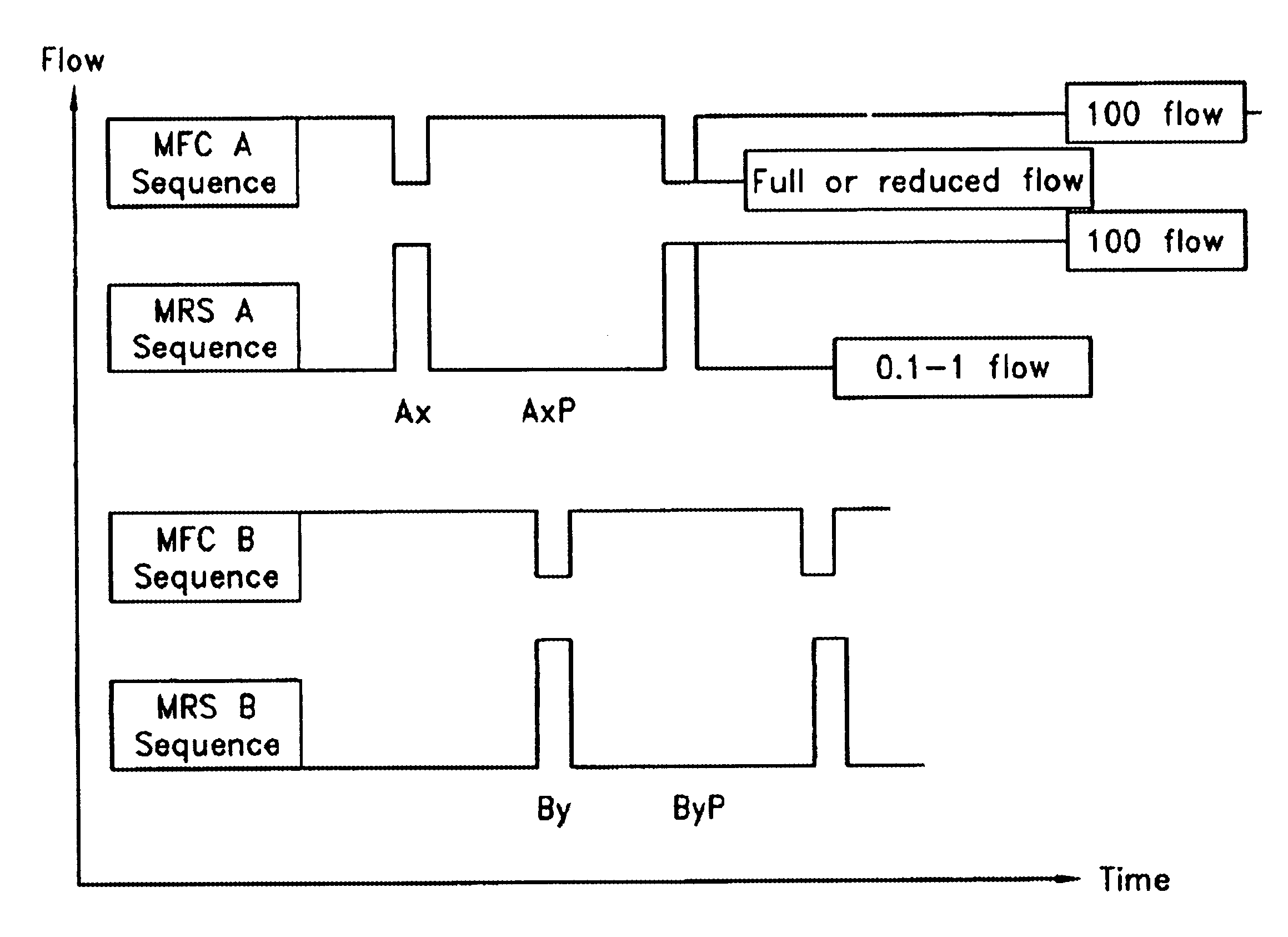
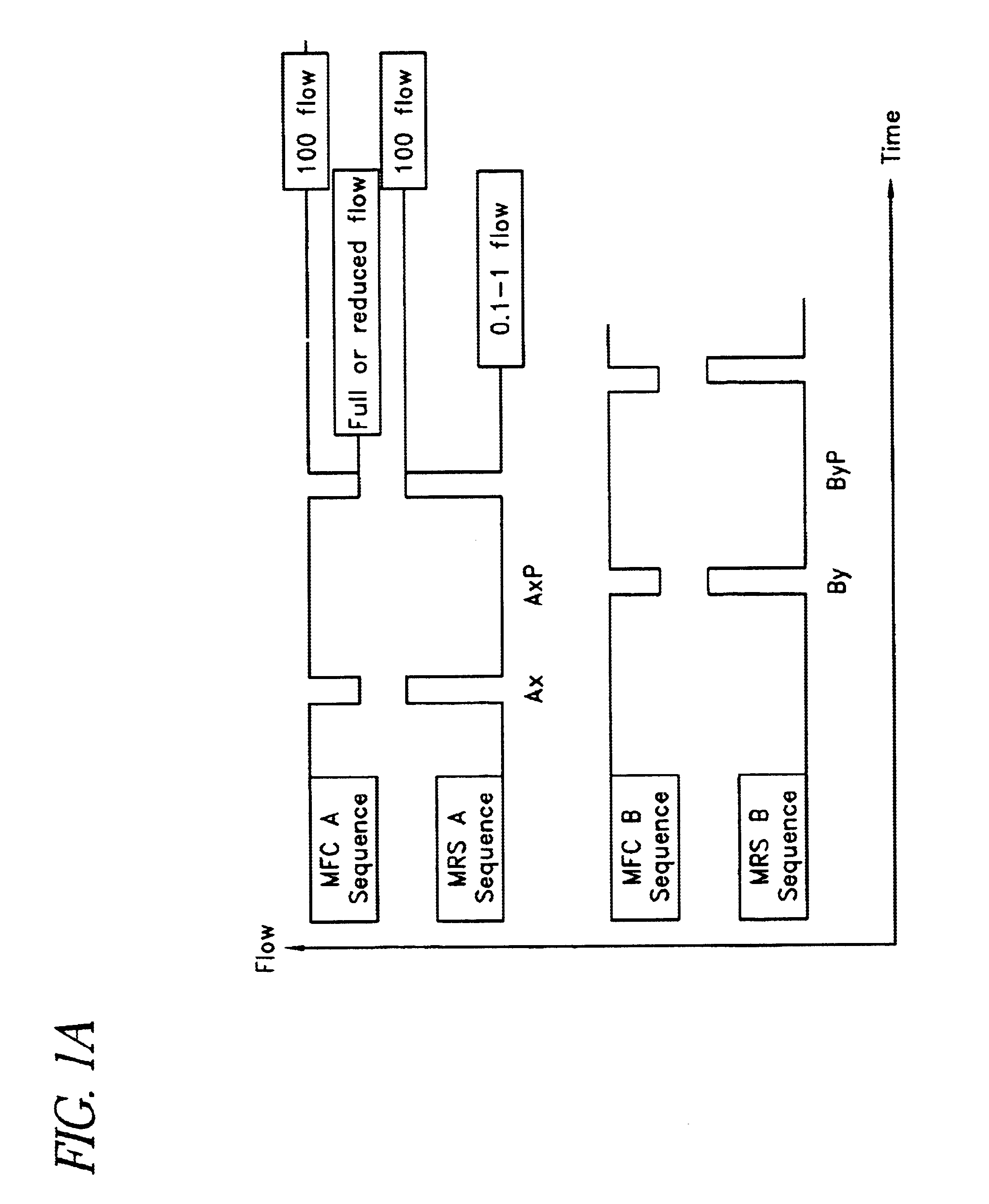
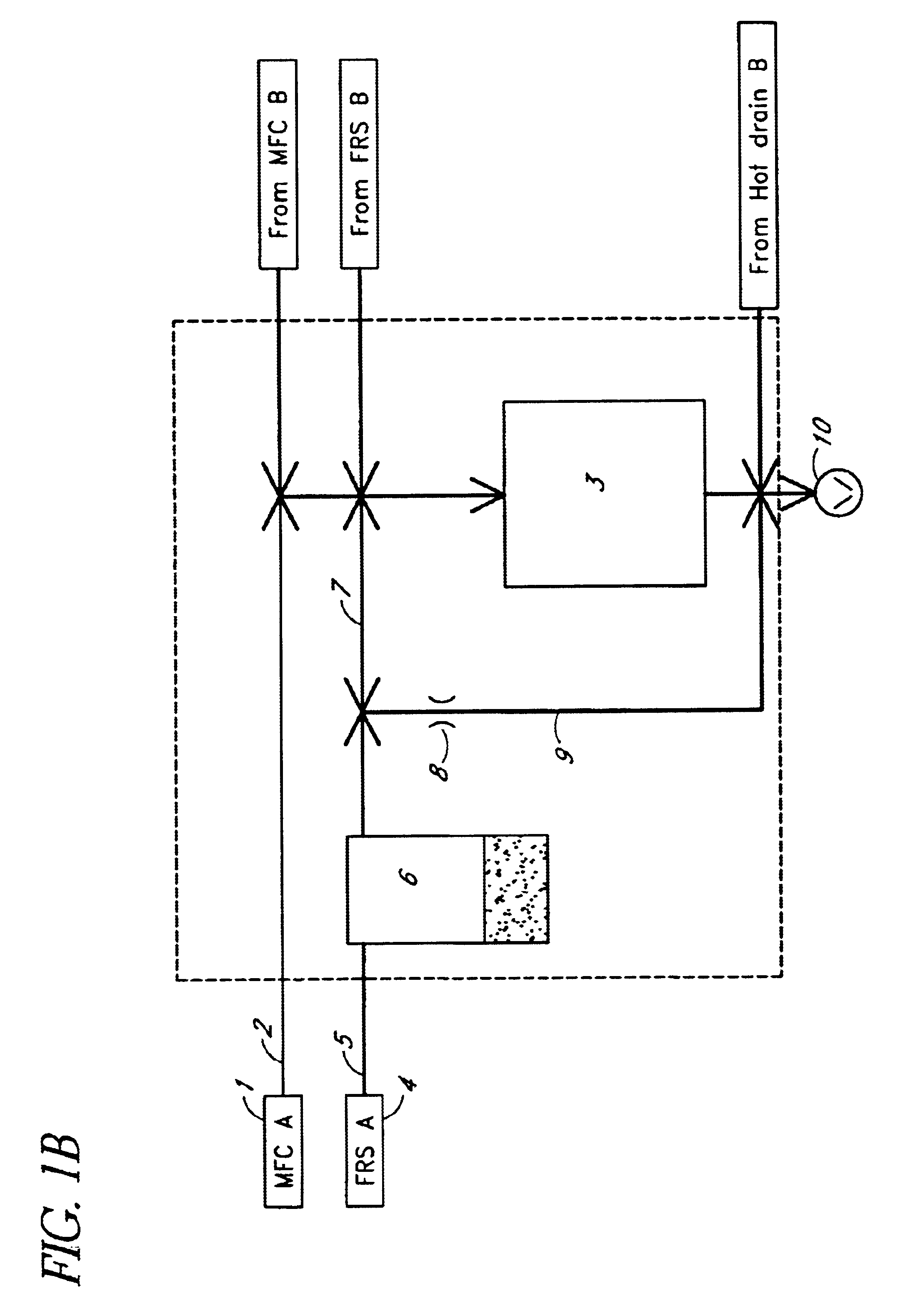
[0016]It is an object of the present invention to eliminate the problems of the prior art and to provide a novel method of growing a thin film onto a substrate placed in a reaction chamber according to the ALD process. In particular, it is an object of the invention to provide a method in which the ALD process can be operated with increased reliability and reduced downtime caused by wear of the process equipment.
[0022]Considerable improvements are obtained by means of the invention. Thus, by means of the presented process, moving mechanical parts can be avoided in the area operated at temperatures above the precursor evaporation temperature. Reactant flow can be blocked without involving any large forces in the operation of the pulsing valves. This will result in negligible wear of valve steams and valve seats. The process is reliable and provides high productivity performance at low costs for any ALD system produced.
[0023]The operation of the present regulating mechanism, in the following also called “inert gas valving” is reliable and it is not sensitive to variations in the chemical character of the precursors. Since it includes no mechanical moving parts, the investment costs and the need for maintenance work is strongly reduced. As will be discussed in more detail below, by the inert gas valving system, pulsing of reactants can be carried out by using only one valve which controls the flow of carrier gas from the source of inactive or inert gas to the precursor source. This valve can be kept at ambient temperature and it is not in direct contact with the reactants. By maintaining the temperature of the draining conduit above the evaporation temperature of the reactant, condensation of the reactant in the hot zone of the apparatus can be avoided. There is no build-up of condensated reactants in the third conduit during the purge phase. All parts of the equipment are kept cleaner and less particles are formed which could be forwarded to the reaction chamber.

Problems solved by technology

Herein arises a risk of microparticle formation already in the in feed lines of the gaseous reactants.
Such microparticles generally have a deteriorating effect on the quality of the deposited thin film.
This puts stringent demands on the valves employed for controlling the dosing.
Also the use of the IGV is somewhat complicated due to solid condensation of the precursor in the ambient operated drain capillary, which can become blocked and by that ending the proper function of the IGV, causing failure of the process.
In single wafer cluster systems, down time for cleaning of drain capillaries and replacing source tubes after each run is not acceptable, contrary to the situation for batch type multi layer processing of thin film displays.
Due to the cyclic nature of ALD processing conventional valves cannot be solo adapted for this kind of a process.
The aggressive source media destroy the valve rapidly at such conditions.
When aggressive precursors are used at elevated temperatures, involving continuous closing actions, the result is rapid wear of the valve seal.
A solenoid valve often creates abrasive products as a result of the steam grinding the solenoid housing.
Mass Flow Controllers (in the following abbreviated “MFC”) are widely used for controlling the precursor dosing into conventional (not pulsing) CVD systems but they cannot be used for fast pulsing ALD systems due to their slow response (long response times).
This is particularly disadvantageous for ALD processing where the valve operates 100 to 10,000 times during one process.

Method used


Image

  • Method of growing a thin film onto a substrate
  • Method of growing a thin film onto a substrate
  • Method of growing a thin film onto a substrate

Examples


Embodiment Construction

[0030]The present invention provides a method of growing a thin film onto a substrate, in which method a substrate is placed in a reaction chamber and said substrate is subjected to surface reactions of a plurality of vapor-phase reactants according to the ALD method to form a thin film.

[0031]The method comprises generally the steps of vaporising a reactant from a reactant source, conducting the vaporised reactant to the reaction chamber via a first conduit, feeding said reactant into said reaction chamber in the form of vapour-phase pulses repeatedly and alternately with vapour-phase pulses of at least one other reactant, and causing said vapour-phase reactants to react with the surface of the substrate at a reaction temperature to form a thin film compound on said substrate. The vaporised reactant can be conducted through a purifier before feeding it into the reaction chamber.

[0032]The present invention comprises basically replacing leak-tight mechanical valves conventionally used...


PUM

PropertyMeasurementUnit
response timeaaaaaaaaaa
temperaturesaaaaaaaaaa
response timeaaaaaaaaaa

Abstract

The present invention relates to the production of thin films. In particular, the invention concerns a method of growing a thin film onto a substrate, in which method the substrate is placed in a reaction chamber and is subjected to surface reactions of a plurality of vapor-phase reactants according to the ALD method. The present invention is based on replacing the mechanical valves conventionally used for regulating the pulsing of the reactants, which valves tend to wear and intrude metallic particles into the process flow, with an improved precursor dosing system. The invention is characterized by choking the reactant flow between the vapour-phase pulses while still allowing a minimum flow of said reactant, and redirecting the reactant at these times to an other destination than the reaction chamber. The redirection is performed with an inactive gas, which is also used for ventilating the reaction chamber between the vapour-phase pulses.

Description

[0001]This is the U.S. national phase under 35 U.S.C. § 371 of International Application PCT / FI01 / 00680, filed Jul. 20, 2001.BACKGROUND OF THE INVENTION[0002]1. Field of the Invention[0003]The present invention relates to the production of thin films. In particular, the invention concerns a method of growing a thin film onto a substrate, in which method the substrate is placed in a reaction chamber and it is subjected to surface reactions of a plurality of vapor-phase reactants according to the ALD method to form a thin film.[0004]2. Description of Related Art[0005]Conventionally, thin films are grown out using vacuum evaporation deposition, Molecular Beam Epitaxy (MBE) and other similar vacuum deposition techniques, different variants of Chemical Vapor Deposition (CVD) (including low-pressure and metallo-organic CVD and plasma-enhanced CVD) or, alternatively, the above-mentioned deposition process based on alternate surface reactions, known in the art as the Atomic Layer Deposition...

Claims


Application Information

Patent Timeline
Patent Type & Authority Patents(United States)
IPC IPC(8): C30B25/14C23C16/455C23C16/44
CPCC23C16/45525C30B25/14C23C16/45544C23C16/44
Inventor LINDFORS, SVENSOININEN, PEKKA T.
Owner ASM INTERNATIONAL
Learn More