Method and apparatus for radiographic imaging

a computed radiography and phosphor plate technology, applied in the field of radiographic imaging, can solve the problems of loss of resolution, interference with electronic signals, and the adjustment mechanism does not employ the very expensive and heavy x and y-slides, and achieve the effect of eliminating sensitivity and other problems and low nois

Inactive Publication Date: 2005-05-17
ESSEX ELECTRO ENGINEERS
View PDF8 Cites 15 Cited by
  • Summary
  • Abstract
  • Description
  • Claims
  • Application Information

AI Technical Summary

Benefits of technology

[0013]In accordance with the illustrated embodiment, a new and improved method and apparatus for radiographic imaging rotates a laser directly rather than using rotating mirrors as in the prior art. The use of the rotating laser to deliver the light directly to transmit fiber ends allows light to move across the fiber ends in a generally straight line path rather than in a sinusoidal path emanating from a rotating mirror as in prior art radiographic imaging systems. In the illustrated embodiment, a thin, straight line of laser pumping light is tilted across multiple fiber ends. For example, the tiled, thin line of pumping light illuminates a small area on a first fiber end on an upstream side of a central fiber which is receiving the most light over its fiber end and while the downstream or trailing fiber is receiving light over only a small area. The tilted line of pulsing light extends both beyond and below the theoretical circle defined by the optical fiber ends such that those fiber ends located at a radius slightly greater or slightly less than the nominal radius for the circle are also illuminated. Thus, there are no dead spots caused by the fiber ends that are located at the nominal radius, which dead spots could cause a loss of resolution and interfere with electronic signal making for measuring the emanated light. Also, the illumination of multiple optical fibers ends assures that no dead spot occurs when the laser light shifts from one fiber end to the next succeeding fiber end. This results in an illumination of the imaging plate and phosphorescent light therefrom that produces signals with low noise as well as eliminate sensitivity and other problems associated with rotating mirrors.

Problems solved by technology

Thus, there are no dead spots caused by the fiber ends that are located at the nominal radius, which dead spots could cause a loss of resolution and interfere with electronic signal making for measuring the emanated light.
Further, the adjustment mechanism does not employ the very expensive and heavy X and Y-slides that also have play or backlash.

Method used


Image

  • Method and apparatus for radiographic imaging
  • Method and apparatus for radiographic imaging
  • Method and apparatus for radiographic imaging

Examples


Embodiment Construction

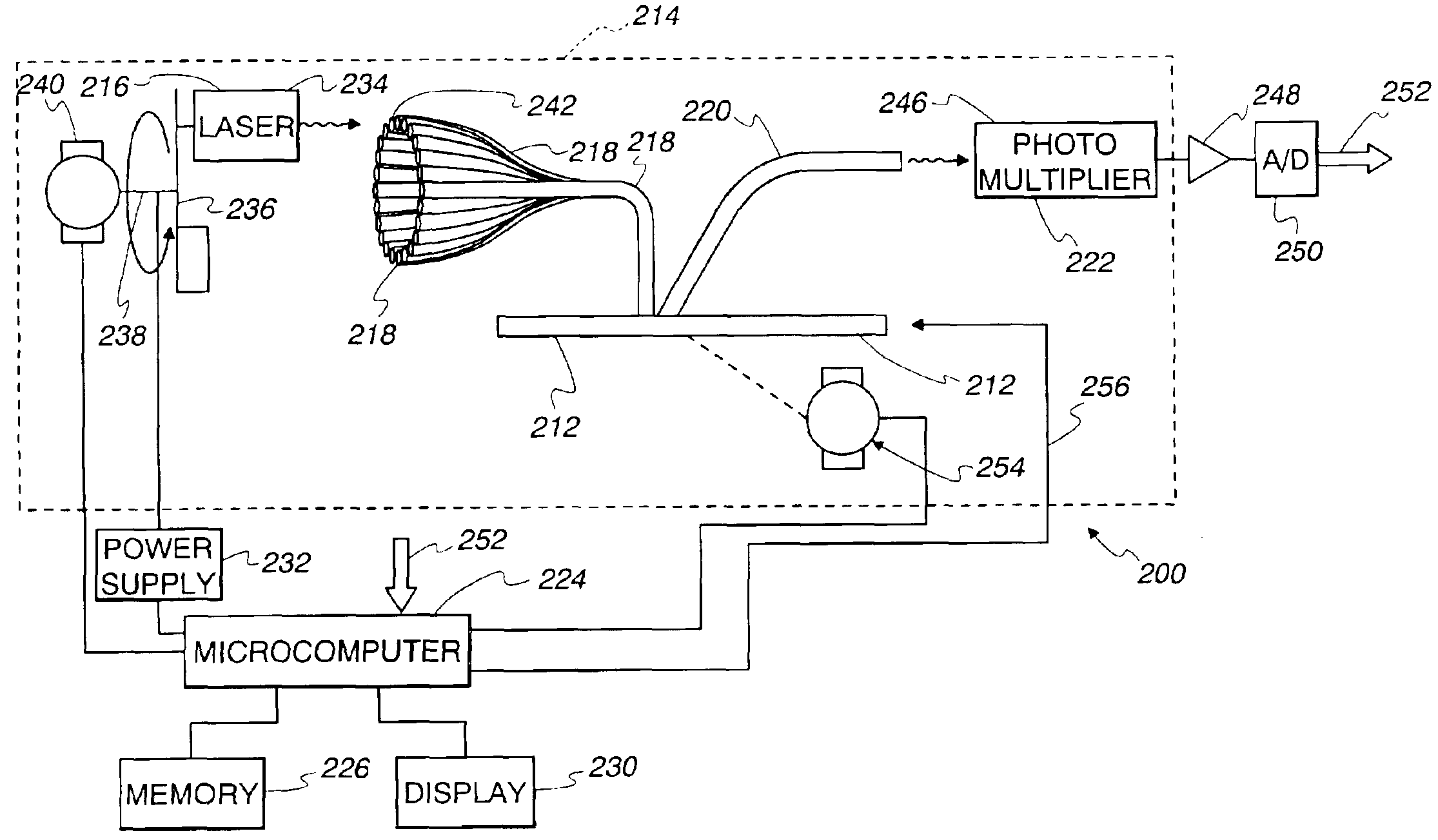
[0048]Referring now to the drawings and especially to FIG. 1, an apparatus embodying the present invention and generally identified by reference numeral 10 is shown therein. The apparatus 10 comprises a computed radiography plate scanner for use in scanning an exposed computed radiography plate 12, which may be a computed radiography plate or a computed radiography sheet. The computed radiography plate scanner 10 produces a visible image of the latent x-ray image stored on the computed radiography plate 12. The computed radiography plate or sheet 12 is normally held in a light-tight cassette but is removable from the cassette for reading or scanning.

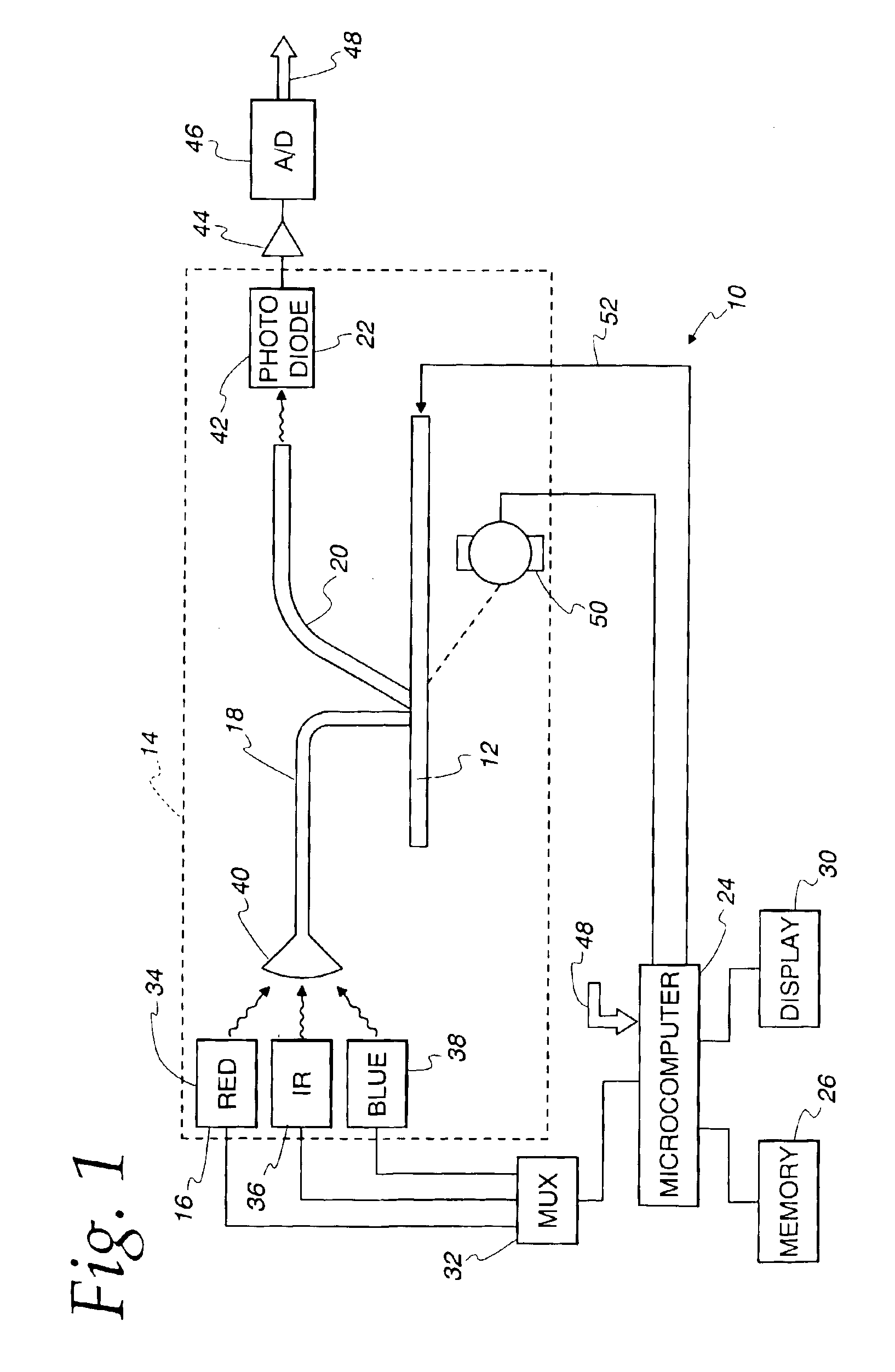
[0049]The apparatus 10 comprises a light-tight enclosure 14 for holding the computed radiography plate 12 during scanning. An optical pump source 16 which may be LEDs in one embodiment or a laser pumping light source 216 (FIG. 8) in another embodiment produces pumping light to be delivered to the computed radiography plate 12 in order to...


PUM


Abstract

An apparatus and method for computed radiography includes a rotating laser as a pumping source for delivering light, without the use of a rotating mirror, successively to ends of each of a plurality of optical fibers arranged in an arc. Opposite ends of the optical fibers are arranged in a linear array to a previously-exposed computed radiography plate having a latent X-ray image formed thereon. The plate is moved with respect to the fibers. Light emitted from the radiographic medium due to excitation by the pumping light travels through a light guide to an optical receiver where an image signal responsive to the light intensity of the emitted light is generated. The image signal is sent to a processor to generate an image representative of the latent X-ray. An erasing of the latent x-ray image may be accomplished in the same machine apparatus that generates the representative image. Preferably, multiple erasure operations are performed with a relaxation period, e.g., three to ten seconds between successive erasing operations. The laser is accurately positioned by an adjustment mechanism in an axial direction to focus the laser light on receiving optical fiber ends and in a radial direction to align the rotational axis substantially coaxially to the axis of the arc for the optical fibers. Electrical power is delivered through a brush and contact to leads in a rotating drive shaft for the rotating laser. The preferred light guide comprises an inlet positioned to receive phosphorescent light from the imaging plate and rearward and forward reflective surfaces for reflecting incoming light back and forth within the light guide that was not directly aligned for travel along a straight line path directly to the light collector, e.g., a photomultiplier tube. A substantial portion of this reflected light will eventually travel forwardly along a path of travel to hit the photomultiplier tube.

Description

CROSS REFERENCE TO RELATED APPLICATIONS[0001]This is a continuation-in-part of U.S. patent application Ser. No. 10 / 281,822 filed Oct. 28, 2002, which is a continuation-in-part of U.S. patent application Ser. No. 09 / 990,164, filed Nov. 21, 2001, now U.S. Pat. No. 6,696,698 which is a continuation-in-part of International Application No. PCT / US01 / 20481, filed Jun. 27, 2001, designating the United States of America, which is a continuation-in-part of U.S. patent application Ser. No. 09 / 721,014, filed Nov. 22, 2000, now U.S. Pat. No. 6,555,838 which claimed priority from U.S. Provisional Patent Application No. 60 / 214,930, filed Jun. 29, 2000. International Application No. PCT / US01 / 20481 filed Jun. 27, 2001 also claimed priority from U.S. Provisional Patent Application No. 60 / 214,930, filed Jun. 29, 2000.BACKGROUND OF THE INVENTION[0002]The invention generally relates to radiographic imaging and, more particularly, relates to a method and apparatus for reading a computed radiography phos...

Claims


Application Information

Patent Timeline
Patent Type & Authority Patents(United States)
IPC IPC(8): G03B42/02
CPCG03B42/02
Inventor LIVINGSTON, TROY W.
Owner ESSEX ELECTRO ENGINEERS
Why Eureka
Try Eureka