Hydraulically balanced reciprocating pulser valve for mud pulse telemetry

a reciprocating, pulse telemetry technology, applied in the direction of instruments, survey, borehole/well accessories, etc., can solve the problems of unacceptable pulse distortion, unacceptable power consumption, low data transmission rate, etc., to increase the effect of increasing the data transmission rate of the mud pulse telemetry system

Active Publication Date: 2005-05-24
BAKER HUGHES INC
View PDF26 Cites 110 Cited by
  • Summary
  • Abstract
  • Description
  • Claims
  • Application Information

AI Technical Summary

Benefits of technology

[0022]In another embodiment, a method is described for increasing the data transmission rate of a mud pulse telemetry system by using a combination of FSK and ASK signals to transmit data, comprising, using an reciprocating pulser to generate pressure pulses; driving a reciprocating poppet at a first predetermined frequency and first predetermined travel distance, and changing the drive signal, at a predetermined poppet position, to simultaneously change to a second predetermined frequency at a second predetermined travel distance, and attaining the second predetermined frequency and second predetermined travel distance in no more than one oscillatory period.
[0023]In another embodiment, a method is described for increasing the data transmission rate of a mud pulse telemetry system by using a combination of PSK and ASK signals to transmit data, comprising, using an reciprocating pulser to generate pressure pulses; driving a reciprocating poppet at a constant frequency at a first predetermined phase angle and first predetermined travel distance, and changing the drive signal, at a predetermined poppet position, to simultaneously change to a second predetermined phase angle at a second predetermined travel distance, and attaining the second predetermined phase angle and second predetermined travel distance in no more than one oscillatory period.

Problems solved by technology

The major disadvantage of available mud pulse valves is the low data transmission rate.
Increasing the data rate with available valve types leads to unacceptably large power consumption, unacceptable pulse distortion, or may be physically impractical due to erosion, washing, and abrasive wear.
Because of their low activation speed, nearly all existing mud pulse valves are only capable of generating discrete pulses.
Because of this high differential pressure, negative pulse valves are more prone to washing.
In general, it is not desirable to bypass flow above the bit into the annulus.
Because of this impact, negative pulsing valves are more prone to mechanical and abrasive wear than positive pulsing valves.
The power consumption of this kind of valve is very small.
The disadvantage of this valve is the passive operated main valve.
With high actuation rates the passive main valve is not able to follow the actively operated pilot valve.
Amplitude coding of the signal is inherently not possible with this kind of continuously rotating device.
On the other hand, both options dramatically increase the inertia and power consumption of the system when changing form one to another speed for signal coding.
The result is excessive wear, fatigue, and failure in operating parts of the system.

Method used


Image

  • Hydraulically balanced reciprocating pulser valve for mud pulse telemetry
  • Hydraulically balanced reciprocating pulser valve for mud pulse telemetry
  • Hydraulically balanced reciprocating pulser valve for mud pulse telemetry

Examples


Embodiment Construction

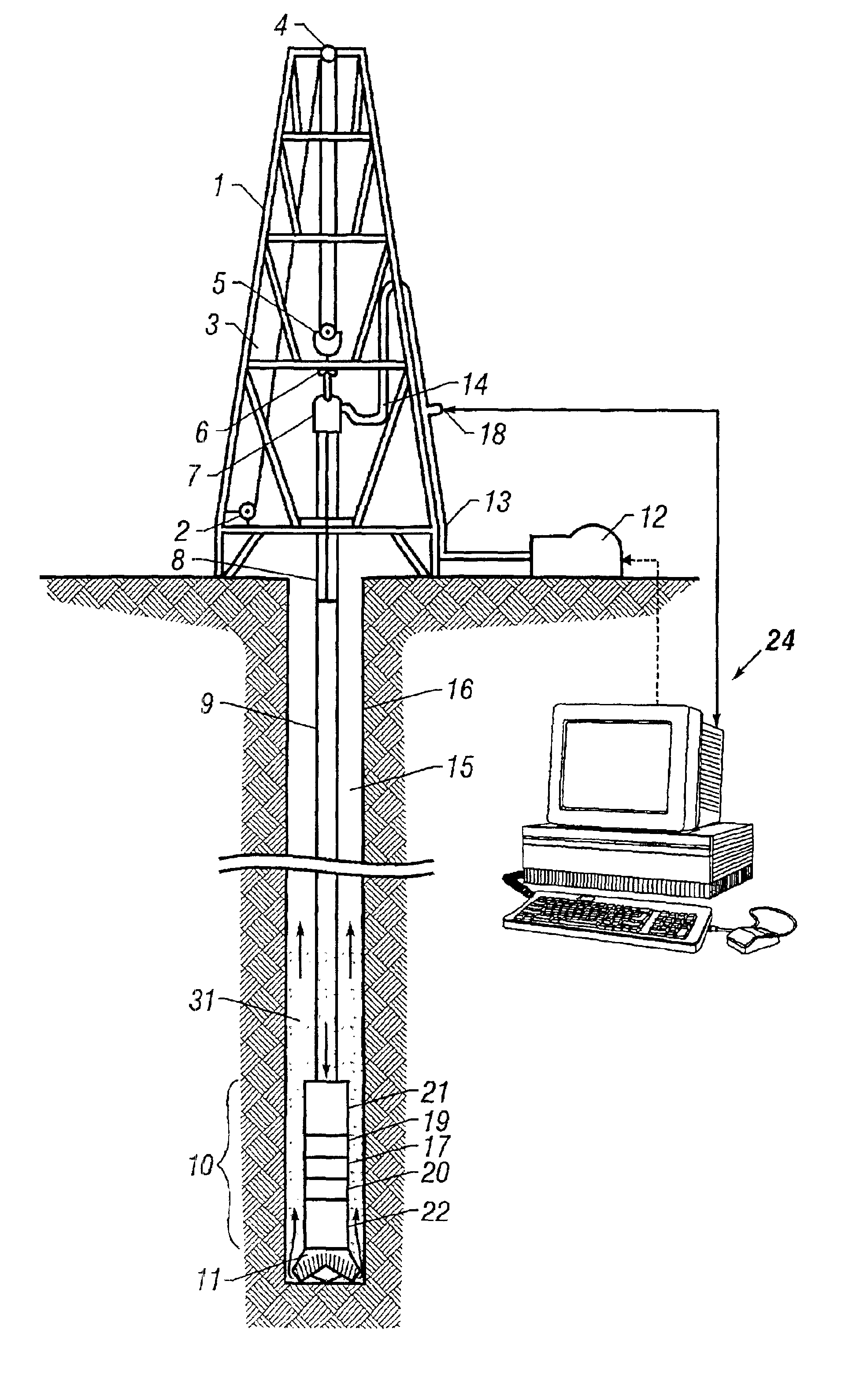
[0032]FIG. 1 is a schematic diagram showing a drilling rig 1 engaged in drilling operations. Drilling fluid 31, also called drilling mud, is circulated by pump 12 through the drill string 9 down through the bottom hole assembly (BHA) 10, through the drill bit 11 and back to the surface through the annulus 15 between the drill string 9 and the borehole wall 16. The BHA 10 may comprise any of a number of sensor modules 17,20,22 which may include formation evaluation sensors and directional sensors. These sensors are well known in the art and are not described further. The BHA 10 also contains a pulser system 19 which induces pressure fluctuations in the mud flow. The pressure fluctuations, or pulses, propagate to the surface through the mud flow in the drill string 9 and are detected at the surface by a sensor 18 and a control unit 24. The sensor 18 is connected to the flow line 13 and may be a pressure transducer, a flow transducer, or a combination of a pressure transducer and a flo...


PUM


Abstract

A reciprocating pulser system for generating pressure fluctuations in a flowing drilling fluid comprising a reciprocating poppet and a stationary valve assembly with axial flow passages. The poppet reciprocates in close proximity to the valve assembly, at least partially blocking the flow through the valve assembly and generating oscillating pressure pulses. The poppet passes through two zero speed positions during each cycle, enabling rapid changes in signal phase, frequency, and / or amplitude thereby facilitating enhanced data encoding. The poppet is driven by a linear electric motor disposed in a lubricant filled housing. In one embodiment, the housing to shaft seal is a flexible bellows. In one embodiment, a force balance spring is used to essentially offset the hydraulic flow forces on the poppet. In one embodiment, a bypass poppet is used to adjust the differential pressure across the valve assembly.

Description

[0001]This application claims the benefit of U.S. Provisional Application No. 60 / 275,342 filed on Mar. 13, 2001.BACKGROUND OF THE INVENTION[0002]1. Field of the Invention[0003]The present invention relates to drilling fluid telemetry systems and, more particularly, to a telemetry system incorporating a reciprocating pulser system for modulating the pressure of a drilling fluid circulating in a drill string within a well bore.[0004]2. Description of the Related Art[0005]Drilling fluid telemetry systems, generally referred to as mud pulse systems, are particularly adapted for telemetry of information from the bottom of a borehole to the surface of the earth during oil well drilling operations. The information telemetered often includes, but is not limited to, parameters of pressure, temperature, direction and deviation of the well bore. Other parameters include logging data such as resistivity of the various layers, sonic density, porosity, induction, self potential and pressure gradi...

Claims


Application Information

Patent Timeline
Patent Type & Authority Patents(United States)
IPC IPC(8): E21B47/18E21B47/12H04L1/00H04L27/00
CPCE21B47/18H04L27/0008H04L1/0001E21B47/182E21B47/20Y10T137/5109
Inventor HAHN, DETLEFPETERS, VOLKERROUATBI, CEDRIC
Owner BAKER HUGHES INC
Why Eureka
Try Eureka