Use of an organic dielectric as a sacrificial layer

a technology of organic dielectrics and dielectric layers, applied in the field of semiconductor fabrication techniques, can solve the problems of difficult and impractical manufacture of small lightweight mechanical or electromechanical parts, difficulty in achieving the miniaturization of mechanical and/or electromechanical systems, and difficulty in performing acidic etchants

Inactive Publication Date: 2005-06-14
HONEYWELL INT INC
View PDF7 Cites 21 Cited by
  • Summary
  • Abstract
  • Description
  • Claims
  • Application Information

AI Technical Summary

Benefits of technology

[0007]The present invention overcomes many of the disadvantages of the prior art by using an organic oxide as a sacrificial layer. The organic oxide can be selectively removed using an organic solvent or etchant such as acetone, oxygen plasma etch or other organic etchant that is less destructive to other layers of the device. Organic solvents or etchants tend to only remove organic materials. This may reduce or eliminate the need for the above-mentioned rinsing and drying steps associated with the use of acidic etchants such as Hydrofluoric Acid. Further, many organic solvents or etchants can more easily reach deeply into very narrow crevices and channels occupied by the sacrificial layer.

Problems solved by technology

Traditionally, the miniaturization of mechanical and / or electromechanical systems has been frustrated by limitations on the manufacture of small lightweight mechanical or electromechanical parts.
The intricacy of the parts made their manufacture on a small scale difficult and impractical.
A limitation of using a silicon dioxide or other inorganic oxide or material is that the acidic etchants often require additional processing steps and can be difficult to perform.
These surfactants can reduce the effectiveness of the Hydrofluoric Acid.
In addition, the removal of the Hydrofluoric Acid etchant from the small crevices and channels can be difficult.
Even with these additional steps, some residual Hydrofluoric Acid often remains, which can reduce the reliability of the resulting structure.
Another limitation is that acidic etchants such as Hydrofluoric Acid tend to attack some metals such as aluminum.
The residual Hydrofluoric Acid can emerge during later processing or testing, and damage the metal layers.
This can compromise the reliability of the devices.

Method used


Image

  • Use of an organic dielectric as a sacrificial layer
  • Use of an organic dielectric as a sacrificial layer
  • Use of an organic dielectric as a sacrificial layer

Examples


Embodiment Construction

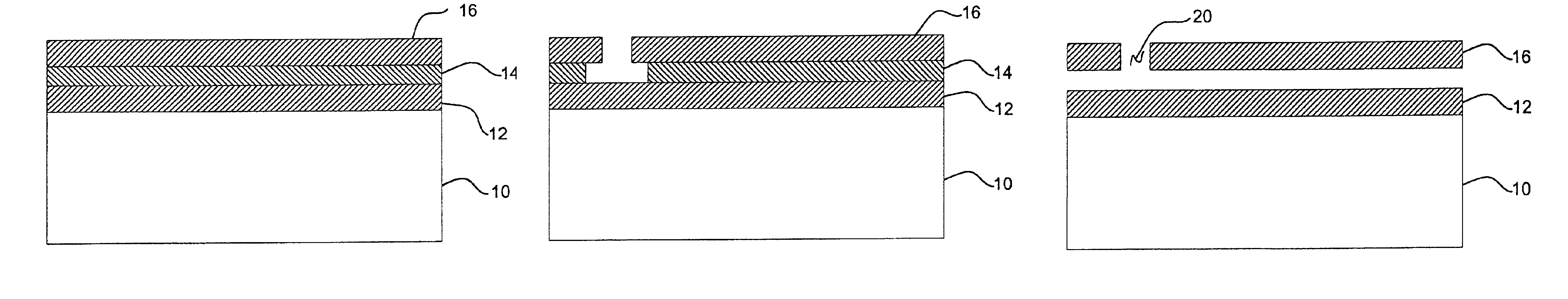
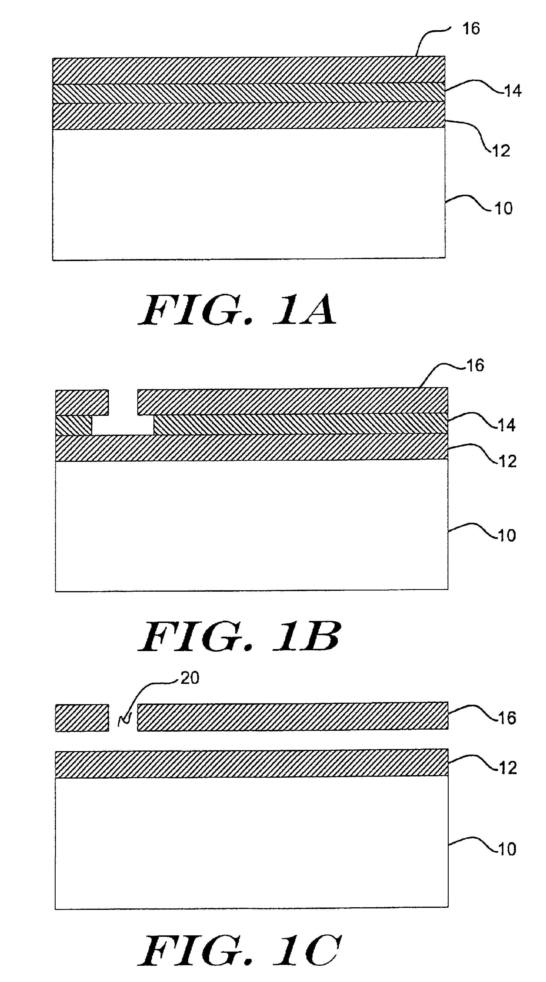
[0022]FIGS. 1A-1C are cross-sectional side views showing an illustrative method for forming a suspended structure. The illustrative suspended structure may be part of, for example, a beam, a slab, a comb, a finger, etc. of a MEMS or other micromachined device, a low capacitance metal interconnect line, an on-chip inductor, or any other suspended structure. FIG. 1A shows a substrate 10 having a first layer 12, a sacrificial second layer 14 provided above the first layer 12, and a third layer 16 provided above the sacrificial second layer 14.

[0023]Although not shown in FIG. 1A, one or more intervening layers may be provided between the substrate 10 and the first layer 12, the first layer 12 and the sacrificial second layer 14, and / or the sacrificial second layer 14 and the third layer 16, as desired. The one or more intervening layers may include, for example, an inorganic dielectric, a metal layer, a polysilicon layer, an optical layer, an etch stop layer, or any other material or ma...


PUM

PropertyMeasurementUnit
temperatureaaaaaaaaaa
glass transition temperatureaaaaaaaaaa

Abstract

A method for using an organic dielectric as a sacrificial layer for forming suspended or otherwise spaced structures. The use of an organic dielectric has a number of advantages, including allowing use of an organic solvent or etch to remove the sacrificial layer. Organic solvents only remove organic materials, and thus do not affect or otherwise damage non-organic layers such as metal layers. This may reduce or eliminate the need for the rinsing and drying steps often associated with the use of acidic etchants such as Hydrofluoric Acid.

Description

FIELD OF THE INVENTION[0001]The present invention generally relates to semiconductor fabrication techniques, and more particularly, to semiconductor fabrication techniques that use a sacrificial layer.BACKGROUND OF THE INVENTION[0002]Traditionally, the miniaturization of mechanical and / or electromechanical systems has been frustrated by limitations on the manufacture of small lightweight mechanical or electromechanical parts. The intricacy of the parts made their manufacture on a small scale difficult and impractical. In recent years, however, and with the proliferation and increased precision in semiconductor fabrication procedures, many of the mechanical and electromechanical structures in a mechanical system may be replaced by MicroElectroMechanical Structures (MEMS) or other micromachined structures that are fabricated using semiconductor fabrication techniques.[0003]During the fabrication of many of these structures, a sacrificial layer is provided to provide temporary support ...

Claims


Application Information

Patent Timeline
Patent Type & Authority Patents(United States)
IPC IPC(8): B81B3/00
CPCB81C1/00476B81C2201/0108
Inventor GUTIERREZ, DAVIDLUCIANI, VINCENT K.BURGESS, MARY C.
Owner HONEYWELL INT INC
Why Eureka
Try Eureka