Cold gas-dynamic spray repair on gas turbine engine components

a gas turbine engine and cold gas technology, applied in the field of turbine engine components, can solve the problems of high rejection rate, costly rework, and difficult application of superalloy materials using more conventional techniques, and achieve the effects of easy welding, high strength, and easy application

Active Publication Date: 2005-06-14
HONEYWELL INT INC
View PDF22 Cites 163 Cited by
  • Summary
  • Abstract
  • Description
  • Claims
  • Application Information

AI Technical Summary

Benefits of technology

[0008]The present invention provides an improved method for repairing high pressure turbine (HPT) components such as blades and vanes in a turbine engine. The method utilizes a cold gas-dynamic spray technique to repair turbine engine components. In the cold gas-dynamic spray process particles at a temperature well below their melting temperature are accelerated and directed to a target surface on the turbine engine component. When the particles strike the target surface, the kinetic energy of the particles is converted into plastic deformation of the particle, causing the particle to form a strong bond with the target surface. Thus, the cold gas-dynamic spray process can apply a powder material to the worn surface of the turbine engine components to restore both geometry and dimension and to repair other defects in the components.
[0009]The cold gas-dynamic spray process can deposit high-strength superalloy materials that are difficult to apply using more conventional techniques. For example, the cold gas-dynamic spray process can be used to apply repair alloys such as high strength nickel base superalloys that in general are not easily welded. When these types of alloys are welded, cracks and other defects in both weld and base material frequently resu

Problems solved by technology

The cold gas-dynamic spray process can deposit high-strength superalloy materials that are difficult to apply using more conventional techniques.
When these types of alloys are welded, cracks and other defects in both weld and base material frequently result, requiring costly reworking and resulting in

Method used


Image

  • Cold gas-dynamic spray repair on gas turbine engine components
  • Cold gas-dynamic spray repair on gas turbine engine components
  • Cold gas-dynamic spray repair on gas turbine engine components

Examples


Embodiment Construction

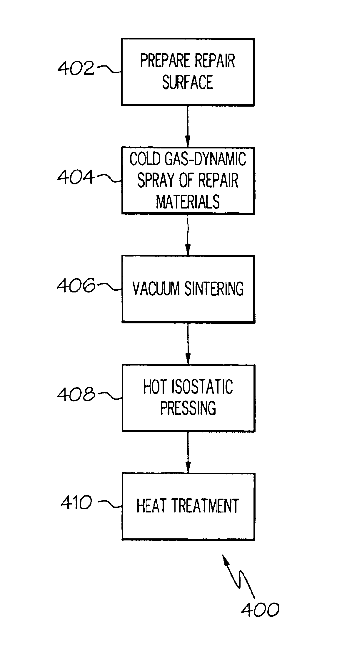
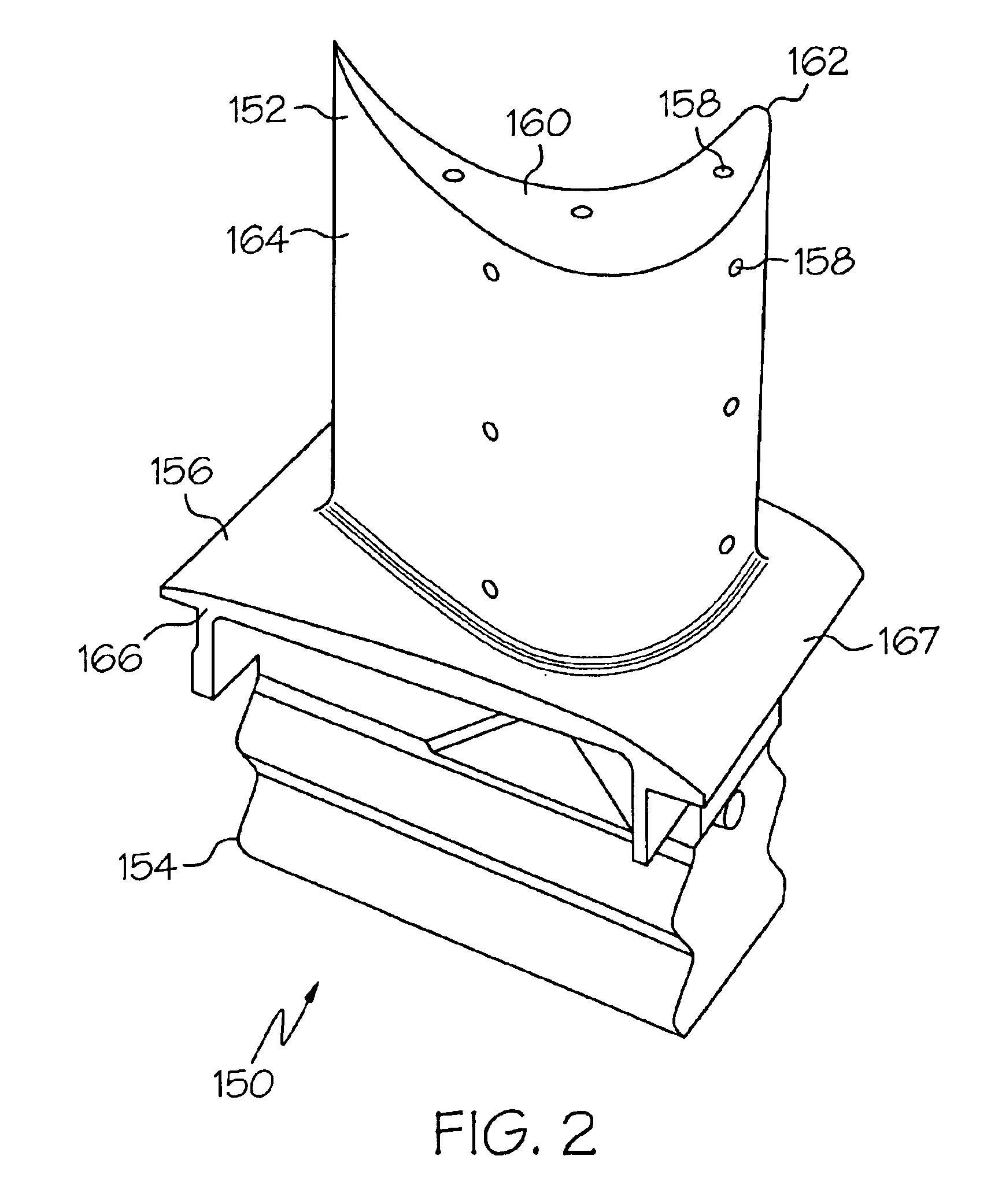
[0017]The present invention provides an improved method for repairing high pressure turbine (HPT) components such as turbine blades. The method utilizes a cold gas-dynamic spray technique to apply high-strength superalloy materials to the worn surface of turbine engine components. These materials can be used to repair degraded components such as blades and vanes caused by erosion, oxidation, corrosion, thermal fatigue cracks and foreign object damage to name several examples.

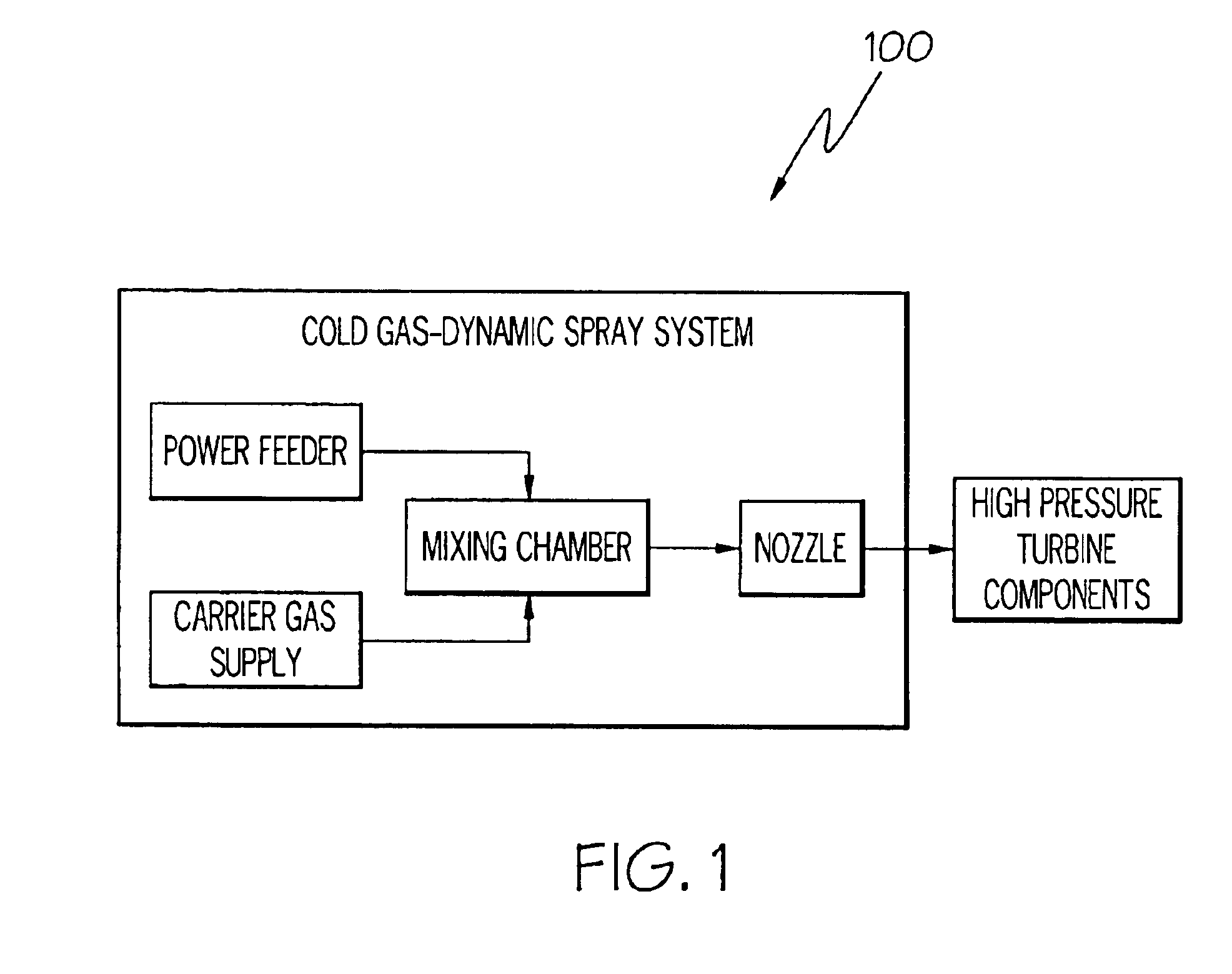
[0018]Turning now to FIG. 1, an exemplary cold gas-dynamic spray system 100 is illustrated schematically. The cold gas-dynamic spray system 100 is a simplified example of a type of system that can be used to repair turbine components. Those skilled in the art will recognize that most typical implementations of cold gas-dynamic spray systems would include additional features and components. The cold-gas-dynamic spray system 100 includes a powder feeder for providing repair powder materials, a carrier gas supply (...


PUM

PropertyMeasurementUnit
Timeaaaaaaaaaa
Timeaaaaaaaaaa
Timeaaaaaaaaaa

Abstract

A new method for repairing turbine engine components is provided. The method utilizes a cold gas-dynamic spray technique to repair degradation on turbine blades, vanes and other components. In the cold gas-dynamic spray process particles at a temperature below their fusing temperature are accelerated and directed to a target surface on the turbine blade. When the particles strike the target surface, the kinetic energy of the particles is converted into plastic deformation of the particle, causing the particle to form a strong bond with the target surface. Post-spray processing is then performed to consolidate and homogenize the applied materials and restore integrity to the material properties in the repaired turbine component. Thus, the cold gas-dynamic spray process and post-spray processing can be employed to effectively repair degraded areas on gas turbine components.

Description

FIELD OF THE INVENTION[0001]This invention generally relates to turbine engines, and more specifically relates to the repair of turbine engine components such as blades and vanes.BACKGROUND OF THE INVENTION[0002]Turbine engines are used as the primary power source for aircraft, in the forms of jet engines and turboprop engines, as auxiliary power sources for driving air compressors, hydraulic pumps, etc, on aircraft, industrial gas turbine (IGT) power generation and as stationary power supplies such as backup electrical generators for hospitals and the like. The same basic power generation principles apply for all these types of turbine engines. Compressed air is mixed with fuel and burned, and the expanding hot combustion gases are directed against stationary turbine vanes in the engine. The vanes turn the high velocity gas flow partially sideways to impinge on the turbine blades mounted on a turbine disk or wheel that is free to rotate.[0003]The force of the impinging gas causes t...

Claims


Application Information

Patent Timeline
IPC IPC(8): B23P6/00C23C24/04C23C26/00C23C24/00F01D5/00
CPCB22F7/08B23P6/007C23C26/00F01D5/005C23C24/04F05D2230/80
Inventor HU, YIPINGMADHAVA, MURALIRENTERIA, FEDERICO
Owner HONEYWELL INT INC
Why Eureka
Try Eureka