[0003]When performing laser interventions, whether in medical surgery, industrial processes, or otherwise, several fundamental considerations are common to most applications and will influence the viability and effectiveness of the invention. To influence the outcome of the intervention, the present invention addresses both the technical innovations involved in an apparatus to facilitate precision laser interventions, and the methods by which a user of such apparatus can achieve a precise result.
[0004]The present invention addresses the following considerations: (1) how does the user identify a target for the laser intervention, (2) how does the user obtain information as to the location and other pertinent features of the target and its important surroundings, (3) how does the user lock onto that target so that the user has the assurance he is affecting the intended target, (4) how does the user localize the effect to the
target site, (5) how does the user treat a large number of individual targets, whether continuously connected, piecewise user treat a large number of individual targets, whether continuously connected, piecewise connected, or disconnected, (6) how does the user assess the effect of the intervention, (7) how does the user correct errors committed either during the course of the intervention or as a result of previous interventions, (8) how does the user react to changing conditions during the course of the intervention to ensure the desired result, and (9) how is safety ensured consistent with U.S. Food and
Drug Agency regulations for
medical instruments and good commercial practice guidelines for industrial applications.
[0005]Of particular interest are medical interventions such as
surgical procedures described by Sklar et al. (U.S. Pat. No. 5,098,426 and U.S.
patent application Ser. No. 475,657 (now abandoned), which are incorporated herein by reference). Although many different kinds of surgery fall within the scope of the present invention, attention is drawn to corneal
refractive surgery in
ophthalmology for the treatment of myopia, hyperopia, and
astigmatism.
[0006]For corneal
refractive surgery, the above nine considerations reduce to the following objectives (in accordance with the present invention described below): (1) identify the location on or in the cornea to be treated, (2) assure that the target is at the desired distance from the apparatus, determine the
topography of the cornea, and determine the location of sensitive tissues to be avoided, (3) identify, quantify, and pursue the motion of suitable part of the cornea which can provide a reference
landmark that will not be altered as a result of the surgical intervention and, likewise, the depth of variations (for example, distance form the
corneal surface to the front objective lens changing due to
blood pressure pulses) of the
corneal surface with respect to the apparatus such that said motions become transparent to the user of the apparatus, (4) provide a laser beam which can be focused onto the precise locations designated by the user such that
peripheral damage is limited to within the tolerable levels both surrounding the
target site and along the laser beam path anterior and posterior to the
target site, (5) provide a
user interface wherein the user can either draw, adjust, or designate particular template patterns overlaid on a
live video image of the cornea and provide the means for converting the template pattern into a sequence of automatic motion instructions which will
traverse the laser beam to focus sequentially on a number of points in
three dimensional space which will in turn replicate the designated template pattern into the corresponding surgical intervention, (6) assure that items (1)-(3) above can be performed continuously during the course of and subsequent to the surgery to monitor the evolution of the pertinent
corneal surface and provide a means of accurate comparison between pre-operative and post-operative conditions, (7) ensure that the structural and physiological damage caused by the surgery to the patient is sufficiently small to permit continued interventions on the same eye, (8) automate the interaction between the various components so that their use is transparent to the user and so that sufficiently fast
electronics accelerate completion of the surgical intervention within pre-selected error tolerances, and (9) provide dependable, fail-safe safety features of sufficiently short reaction times to prevent any chance of injury to sensitive corneal tissues. With these objectives fulfilled, the speed of surgery will no longer be limited by human
perception delay and response times but by the capability of the apparatus to recognize changing patterns and adjust to the new conditions. Equally important, the accuracy of the surgery will not be constrained by the bounds of human dexterity, but by the mechanical resolution, precision, and response of advanced electro-optical and electromechanical systems.
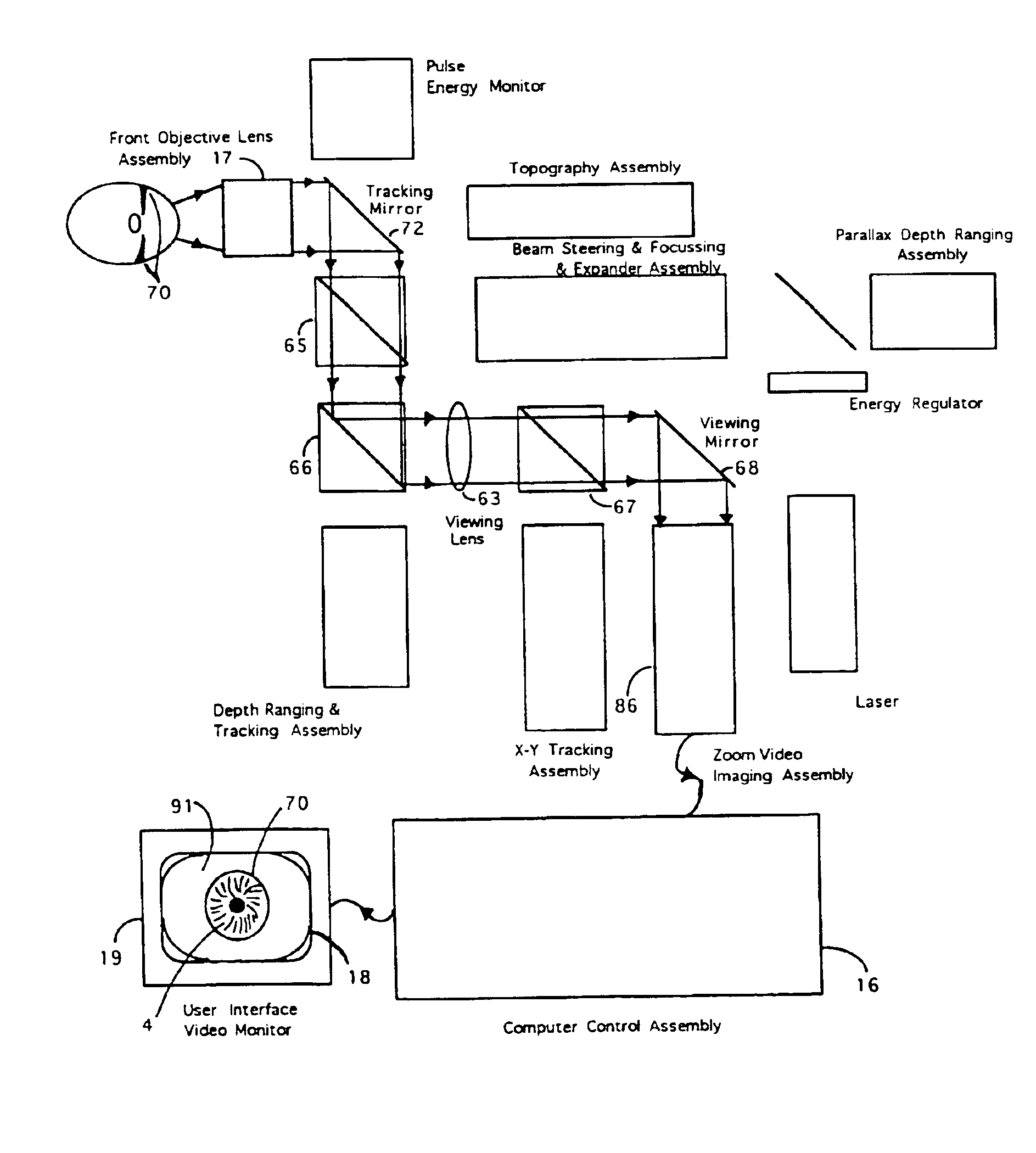
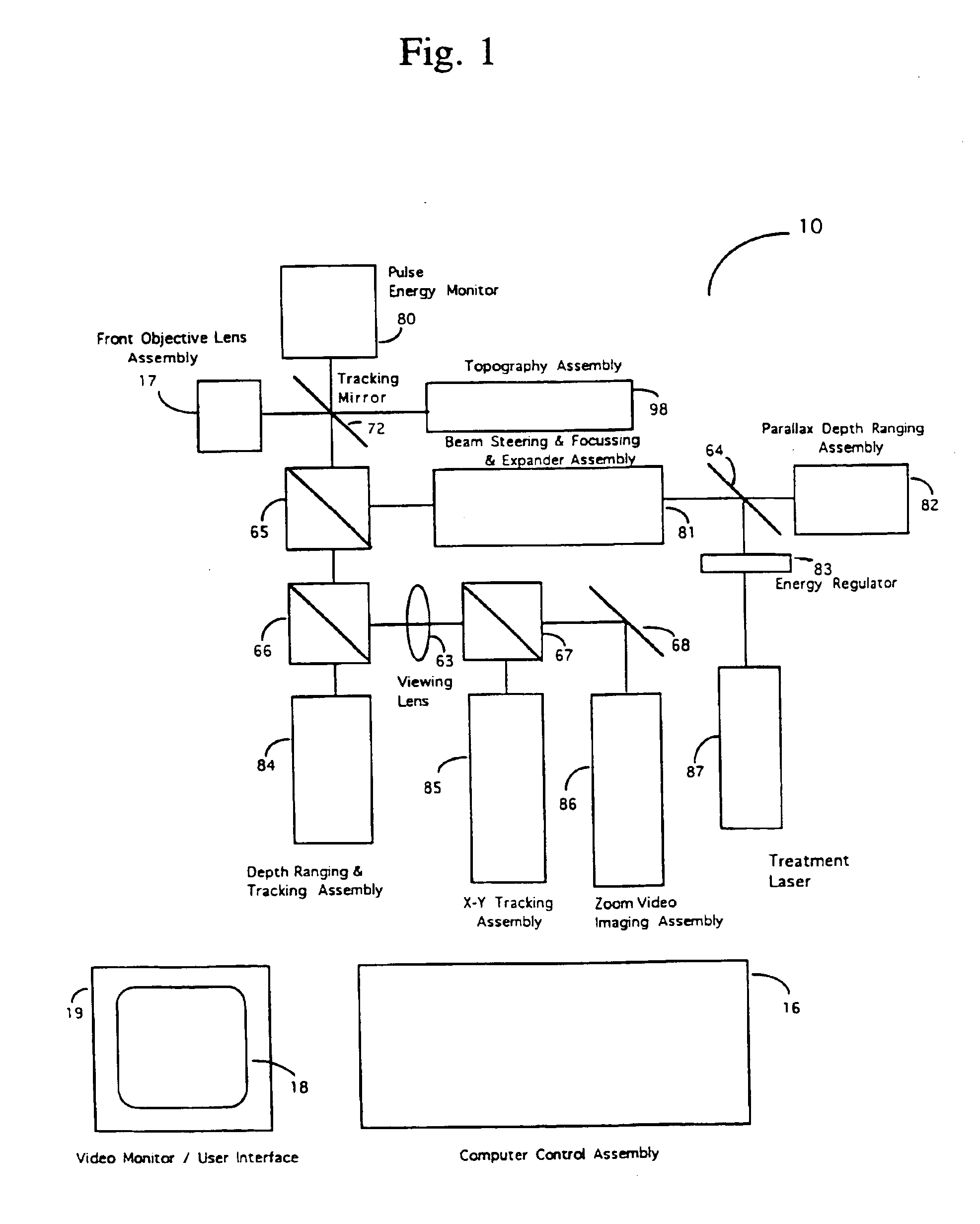
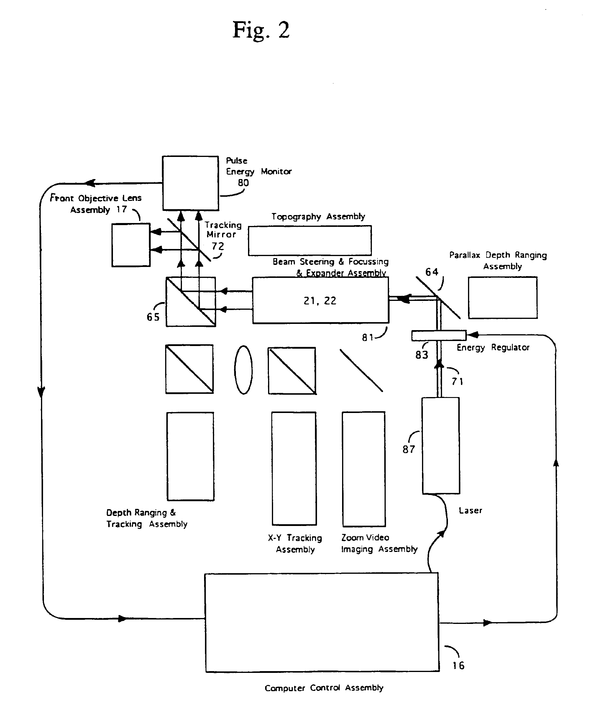
[0007]There are substantial number of different functions which the apparatus of the present invention addresses. Each of the complementary and at times competing, functions requires its own technologies and corresponding subassemblies. The present invention describes how these various technologies integrate into a unified
workstation to perform specific interventions most efficaciously. For example, for corneal
refractive surgery, as per (1) and (2) above, identify the location to be treated on or in the cornea, the surgeon / user would use a combination of
video imaging and automated diagnostic devices as described in Sklar et al. (U.S. Pat. No. 5,098,426 and U.S. patent application Ser. No. 475,657 (now abandoned)), depth
ranging techniques as described in Fountain (U.S. Pat. No. 5,162,641), surface topographical techniques, as described in Sklar (U.S. Pat. No. 5,054,907) together with
signal enhancement techniques for obtaining curvatures and charting the contours of the corneal surface as described by McMillan and Sklar (U.S. Pat. No. 5,170,193), profilometry methods as disclosed by McMillan et al. (U.S. Pat. No. 5,283,598),
image stabilization techniques as described by Fountain (U.S. Pat. No. 5,162,641), which may all be combined using techniques as described by Sklar et al. (U.S. Pat. No. 5,098,426 and U.S. patent application Ser. No. 475,657 (now abandoned)). All of the above listed patent applications and the patent of Fountain (U.S. Pat. No. 5,391,165) are herein incorporated by reference.
[0008]Aspects of the above-referenced disclosures are further used to provide means of satisfying the key aspects (3)-(9) noted above, such as
verification of target distance from the apparatus, tracking the motion of the cornea in three dimensions, providing a laser whose parameters can be tuned to selectively generate photodisruption of tissues or photocoagulation as desired, automatically targeting and aiming the laser beam to precise locations, and supplying a surgeon / user with a relatively simple means of using the apparatus through a computer interface.

