Optical pick-up, optical disk apparatus and information processing apparatus

a technology of optical disk and optical pickup, applied in the direction of digital signal error detection/correction, instruments, recording signal processing, etc., can solve the problems of te signal offset, weak te signal strength, and detection of focus error signals, so as to reduce the manhour for assembling steps, and prevent the offset of the focus error signal

Inactive Publication Date: 2005-08-09
PANASONIC CORP
View PDF17 Cites 40 Cited by
  • Summary
  • Abstract
  • Description
  • Claims
  • Application Information

AI Technical Summary

Benefits of technology

[0022]In order to solve the above-mentioned conventional problems, a first optical pick-up of the present invention includes a first semiconductor laser light source for emitting a light beam with wavelength λ1; a second semiconductor laser light source for emitting a light beam with wavelength λ2; a converging optical system for receiving the light beams emitted from the first and second semiconductor laser light sources and for converging the received light beams into a microscopic spot on an optical disk; a diffractive element for diffracting the light beam reflected by the optical disk; and a photo detecting portion for receiving the diffracted light diffracted by the diffractive element and for outputting an electric signal proportional to the amount of the diffracted light, wherein the photo detecting portion includes a photo detecting portion PD0 for receiving a +first order diffracted light from the diffractive element, and wherein a distance d1 between the center of the photo detecting portion PD0 and the light emitting spot of the first semiconductor laser light source and a distance d2 between the center of the photo detecting portion PD0 and the light emitting spot of the second semiconductor laser light source substantially satisfy the following relationship:λ1 / λ2=d1 / d2.According to the above-mentioned optical pickup, the photo detecting portion can be shared by both wavelengths, and the number of the photo detecting portions can be reduced. Therefore, it is possible to reduce the area of the photodetector and the number of the circuit elements converting output signals into current / voltage signals, thus enabling the cost reduction and the miniaturization of the apparatus to be realized.
[0023]A second optical pick-up of the present invention includes a first semiconductor laser light source for emitting a light beam with wavelength λ1; a second semiconductor laser light source for emitting a light beam with wavelength λ2; a converging optical system for receiving the light beams emitted from the first and second semiconductor laser light sources and for converging the received light beams into a microscopic spot on an optical disk; a diffractive element for diffracting the light beam reflected by the optical disk; and a photo detecting portion for receiving the diffracted light diffracted by the diffractive element and for outputting an electric signal proportional to the amount of the diffracted light, wherein the photo detecting means includes a photo detecting portion PD0 for receiving a +first order diffracted light from the diffractive element, and a distance d1 between the center of the photo detecting portion PD0 and the light emitting spot of the first semiconductor laser light source and a distance d2 between the center of the photo detecting portion PD0 and the light emitting spot of the second semiconductor laser light source, and a distance d12 between the light emitting spots of the first and second semiconductor laser light sources satisfy the following relationship:d2=d1+d12and substantially satisfy the following relationships:d1=λ1·d12 / (λ2−λ1)d2=λ2·d12 / (λ2−λ1).According the above-mentioned optical pick-up, with respect to the predetermined distance between the light emitting spots and wavelength, the photo detecting portion can be shared by both wavelengths, and the number of the photo detecting portions can be reduced. Therefore, it is possible to reduce the area of the photodetector and the number of the circuit elements converting output signals into current / voltage signals, thus enabling the cost reduction and the miniaturization of the apparatus to be realized.

Problems solved by technology

Furthermore, in this configuration, a focus error signal is detected by a knife edge method.
However, as compared with DVD-RAM, the strength of TE signals is weak.
Furthermore, the PP method has a problem in that a TE signal offset occurs due to the lens shift.
However, there is no means for solving the problem of offset in the case of CD-ROM or CD-R.
When the main beam is deviated from the center of the track, one of the sub-beams approaches to the center of the track and the other sub-beam is distant from the center of the track, thus causing the difference in the amount of reflected return light.
However, in conventional methods, there is no specific example of the configuration capable of corresponding to three types of TE signals detection methods, i.e. the phase difference method, PP method, and 3-beam method.

Method used


Image

  • Optical pick-up, optical disk apparatus and information processing apparatus
  • Optical pick-up, optical disk apparatus and information processing apparatus
  • Optical pick-up, optical disk apparatus and information processing apparatus

Examples


embodiment 1

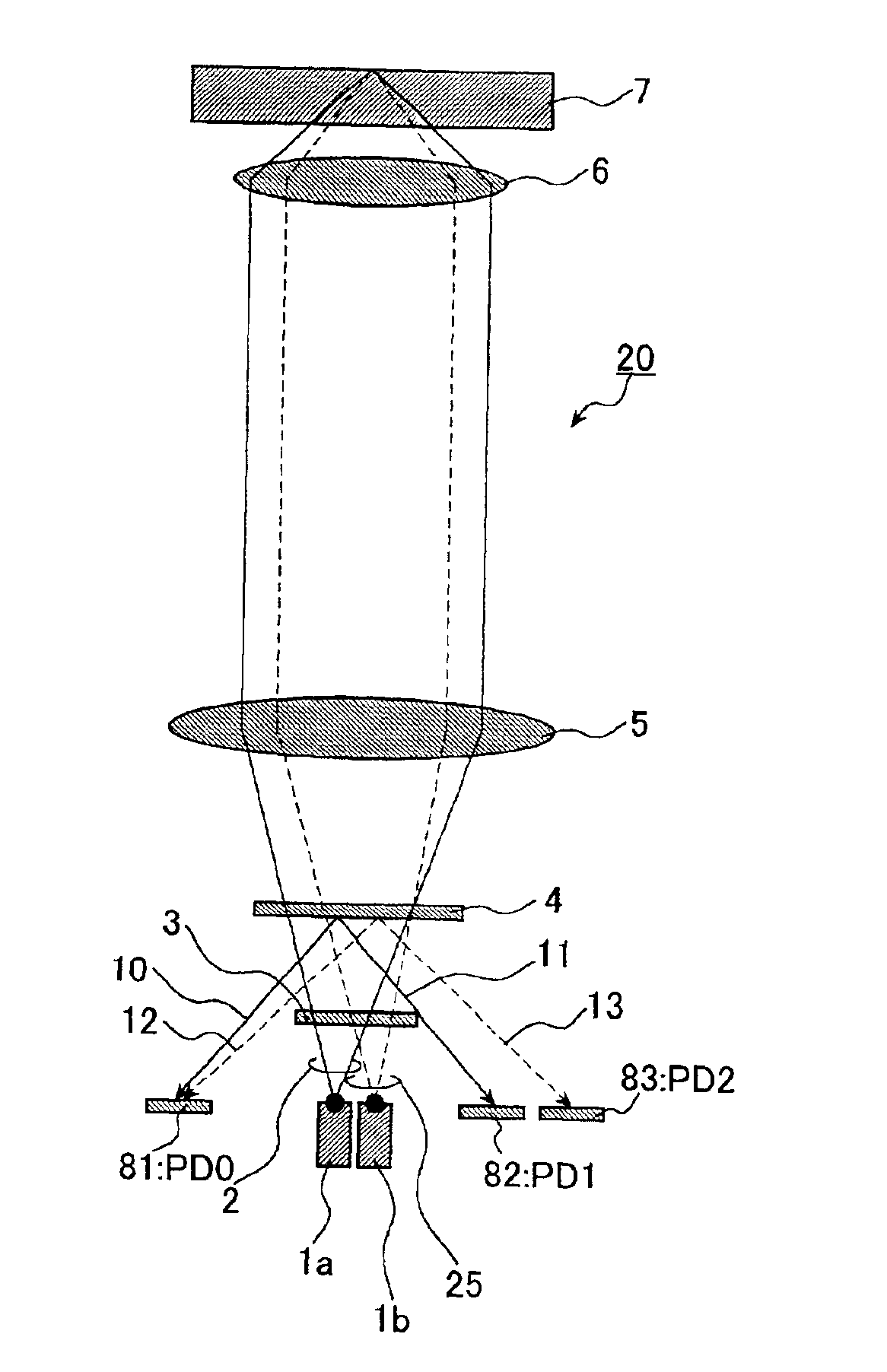
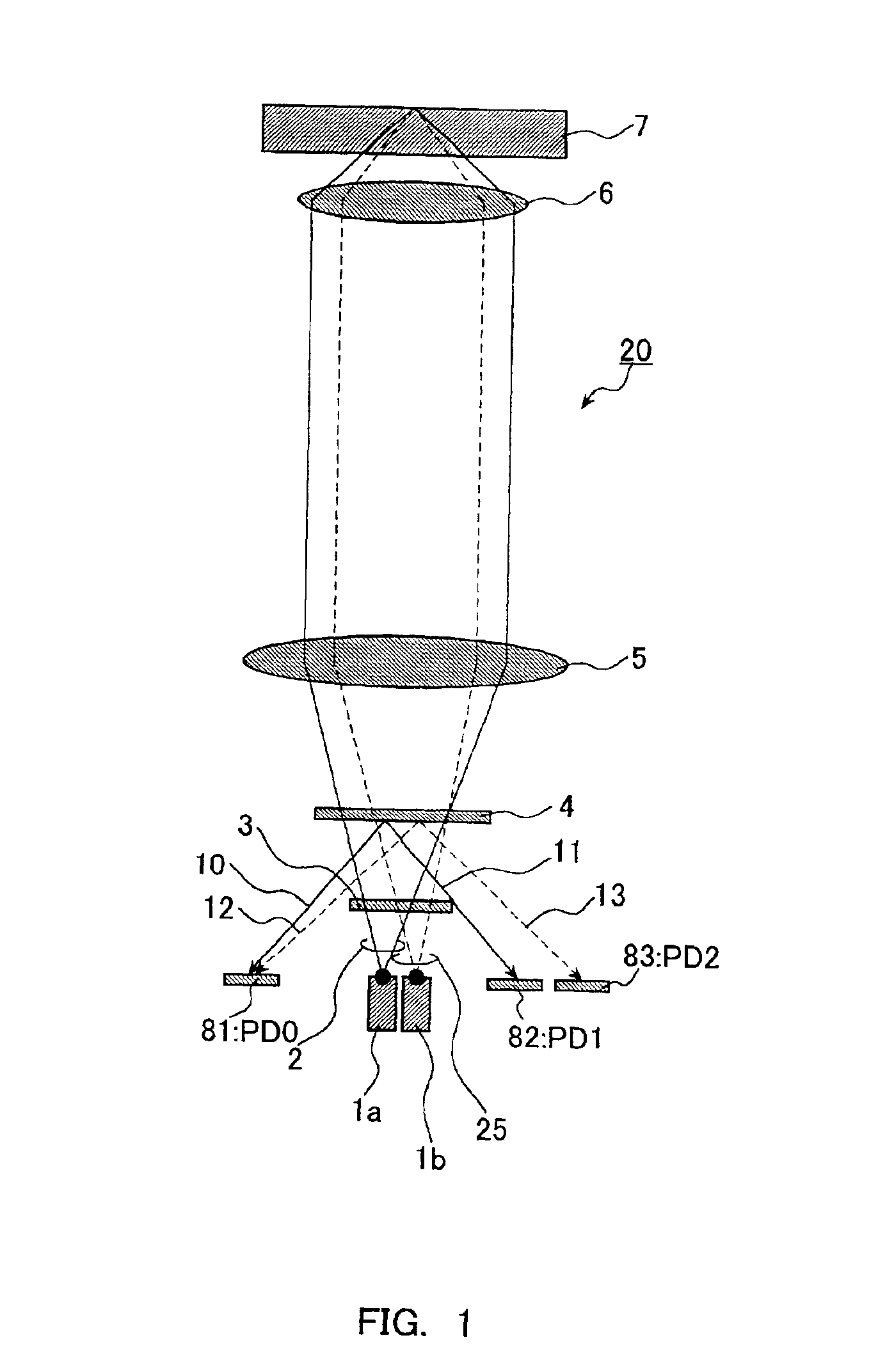
[0085]FIG. 1 is a view showing a configuration of an optical pick-up according to a first embodiment of the present invention. In FIG. 1, a semiconductor laser light source includes a red laser 1a and an infrared laser 1b. Reference numerals 81, 82 and 83 denote optical detecting portions (PD0, PD1 and PD2) carrying out a photoelectric conversion, that is, receiving light beams and converting the received light beams into electric signals such as electric current. Reference numeral 3 denotes a grating; and 4 denotes a diffractive element, and as the diffractive element, an optical element in which a phase or a transmissivity having a periodical structure is used. In the diffractive element 4, the period or direction, that is, a grating vector, may vary depending on the parts. A typical example of the diffractive element is a hologram, for example, a phase-type hologram. In the explanation below, the diffractive element will be explained as taking a hologram 4 as an example. Referenc...

second embodiment

(Second Embodiment)

[0106]FIGS. 5 and 6 show a configuration of a thin optical pick-up by using a rising mirror of the second embodiment. FIG. 5 shows a case where information is reproduced on a DVD optical disk by using an emitted red light beam 2. FIG. 6 shows a case where information is reproduced on a DVD optical disk by using an emitted infrared light beam 25.

[0107]The light collimated by the collimating lens 5 into nearly parallel beam of light is reflected by the rising mirror 17 and changes the direction of moving, thereby reducing the size (thickness) of the optical pick-up in the direction perpendicular to the plane of the optical disk 7.

[0108]As shown in FIG. 5, a wavelength selection aperture 18 just serves as a transparent substrate with respect to the red light beam 2 and does not act on it. As shown in FIG. 6, the wavelength selection aperture 18 shields light beams distant from the optical axis with respect to the infrared light beam 25. This wavelength selection aper...

third embodiment

(Third Embodiment)

[0111]FIG. 7 shows a photodetector 8 according to a third embodiment. The photodetector 8 has a configuration in which the red laser 1a and the infrared laser 1b, and the photo detecting portions 81 to 83 are integrated. The photodetector 8 includes photo detecting portions 81 to 83 formed on a silicone substrate, etc. By integrating all of the photo detecting portions on one substrate like this, it is possible to reduce the manhours for electrical connection and to determine the relative positions between the photodetectors with high precision. Reference numeral 1 denotes a laser light source such as a semiconductor laser in which a red laser and an infrared laser are integrated monolithically. By forming lasers having two different wavelengths on one chip of the semiconductor laser light source 1 like this, the distance between the light emitting spot of the red laser and the light emitting spot of the infrared laser can be set precisely in a μm order or sub μm o...


PUM

PropertyMeasurementUnit
wavelengthaaaaaaaaaa
wavelength λ2aaaaaaaaaa

Abstract

An optical pick-up capable of reproducing information excellently on both CD and DVD, which are significantly different in terms of three kinds of factors, a base material thickness, a wavelength of a light source, and NA, and detecting TE signals by three kinds of methods, that is, the phase difference method, the PP method, and the 3-beam method, which are necessary to record and reproduce information. The optical pick-up is formed by integrating laser light sources having two kinds of wavelengths (λ1, λ2) for detecting TE signals; photodetectors, and hologram for generating the diffracted light for detecting signals. The distance d1 between the center of the photo detecting portion PD0 and the light emitting spot of the first semiconductor laser light source and a distance d2 between the center of the photo detecting portion PD0 and the light emitting spot of the second semiconductor laser light source substantially satisfy the following relationship:λ1 / λ2=d1 / d2.

Description

BACKGROUND OF THE INVENTION[0001]1. Field of the Invention[0002]The present invention relates to an optical pick-up used for recording / reproducing or erasing information on an optical disk, an optical disk apparatus, and an information processing apparatus using the same.[0003]2. Description of the Prior Art[0004]Optical memory technology that uses optical disks having a pit pattern as high-density, large-capacity information storage media has been expanding its application from digital audio disks to video disks, document file disks, and further to data files, etc. In recent years, a high-density optical disk such as DVD-ROM etc. using a visible red laser of wavelength of 630 nm to 670 nm as a light source has become prevalent. Furthermore, an optical disk (DVD-RAM) capable of high density recording has been commercialized. A large capacity of digital data has been able to be recorded on an optical disk easily. Furthermore, CD-R that is highly compatible with CD, which has been use...

Claims


Application Information

Patent Timeline
Patent Type & Authority Patents(United States)
IPC IPC(8): G11B31/00G11B19/12G11B7/12G11B7/125G11B7/09G11B7/135G11B7/00G11B7/13
CPCG11B7/1205G11B7/1275G11B7/131G11B7/1353G11B19/125G11B31/00G11B7/0901G11B7/0903G11B7/0906G11B7/0912G11B2007/0006G11B7/123
Inventor KOMMA, YOSHIAKIMORI, EISHINHOTTA, NAOYA
Owner PANASONIC CORP
Why Eureka
Try Eureka