
Advanced microelectronic heat dissipation package and method for its manufacture

a technology of heat dissipation package and microelectronic device, which is applied in the field of packaging and heat dissipation, can solve the problems of microelectronic device running into basic barriers, heat generation, power drain, and new failure modes, and achieves the effect of being easily miniaturized and cheaply produced

Inactive Publication Date: 2005-08-30
ADVANCED MATERIALS TECHNOLOGIES
View PDF24 Cites 18 Cited by
  • Summary
  • Abstract
  • Description
  • Claims
  • Application Information

AI Technical Summary

Benefits of technology

[0013]It has been an object of at least one embodiment of the present invention to provide a heat pipe that can be cheaply produced and readily miniaturized.
[0014]Another object of at least one embodiment of the present invention has been that said heat pipe be readily made part of a package suitable for housing, and rapidly removing, heat generated by a semiconductor chip.

Problems solved by technology

As the world moves towards higher performance communication and computer systems, microelectronic devices are running into basic barriers related to heat dissipation.
The active designs require fans or pumps to circulate fluids for heat extraction, often leading to heat generation, power drain, and new failure modes.
The latter choices suffer from high thermal expansion coefficients which induce a new failure mechanism through thermal fatigue, associated with turning on (heating up) and turning off (cooling down) an electronic device.
In order to sustain the desired thermal expansion match with silicon while maximizing thermal conductivity, the top materials then tend to be heavy, expensive, and modest in thermal conductivity.
Only diamond provides a high thermal conductivity with low thermal expansion, but its cost is prohibitive.
However, even these two-material combinations are limited by the thermal conductivity of the base.
This is still half that possible with pure copper, but, again, still fails to satisfy the thermal expansion requirement.

Method used


Image

  • Advanced microelectronic heat dissipation package and method for its manufacture
  • Advanced microelectronic heat dissipation package and method for its manufacture
  • Advanced microelectronic heat dissipation package and method for its manufacture

Examples


example

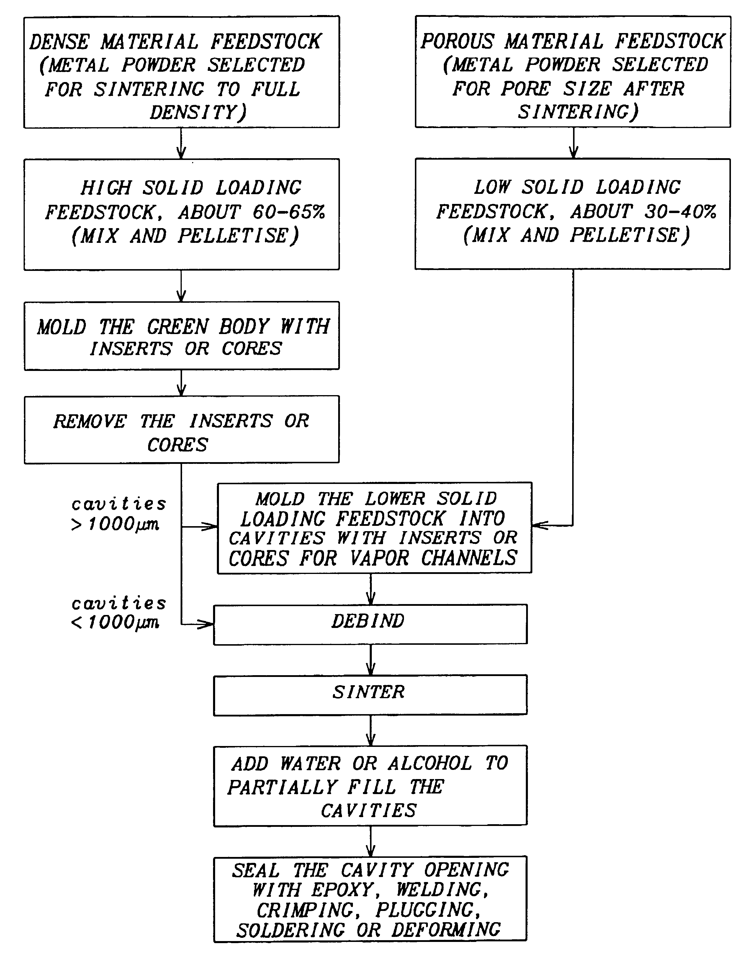
[0036]A 99.85% pure copper powder with a mean particle size of 15 μm is mixed with an organic binder composed of paraffin wax, micropulver wax, polyethylene, and stearic acid to form a first feedstock. Said 15 μm copper powder comprises 50 volume percent of the said first feedstock. A 99.88% pure copper powder with a mean particle size of 50 μm is mixed with the same binder composition to form a second feedstock. Said 50 μm copper powder comprises 35 vol. % of the said second feedstock. The first feedstock is molded into the shape of a cylindrical housing measuring 18 mm long and 12.5 mm in diameter.

[0037]A cylindrical steel insert forms a cavity measuring 16 mm long and 5 mm in diameter. A 16 mm long and 3 mm in diameter insert consisting of polyethylene and 20% paraffin wax is then added to the cavity of the green housing and the second feedstock is molded into the open portion of the cavity. The green body is freed of all organic binder by heating in a controlled furnace over a p...


PUM

PropertyMeasurementUnit
Lengthaaaaaaaaaa
Lengthaaaaaaaaaa
Lengthaaaaaaaaaa

Abstract

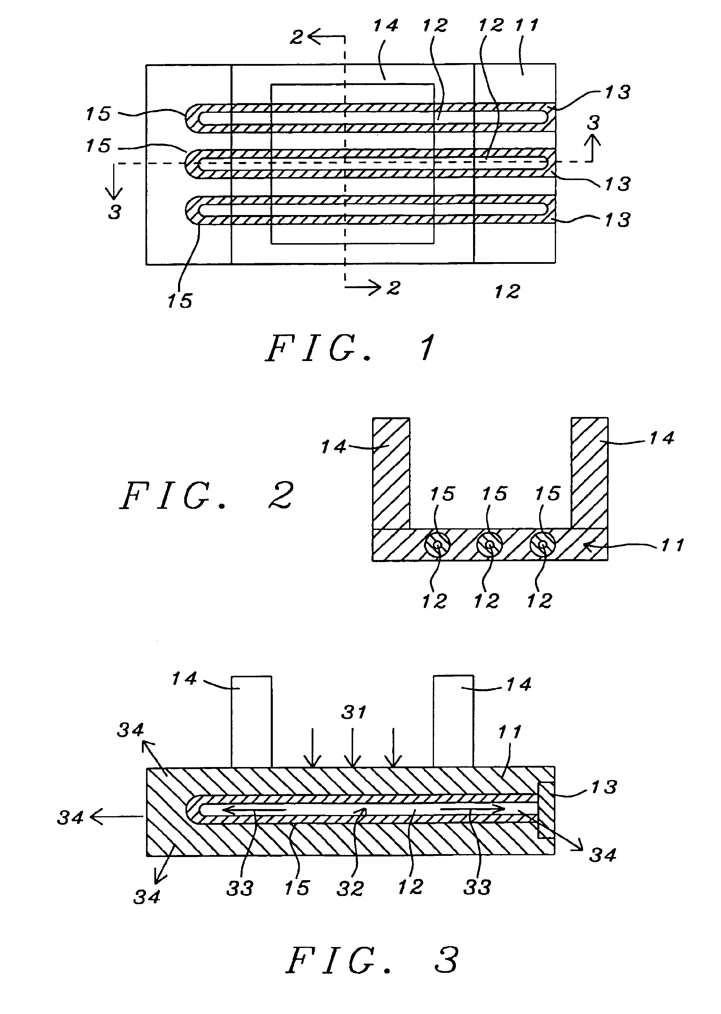
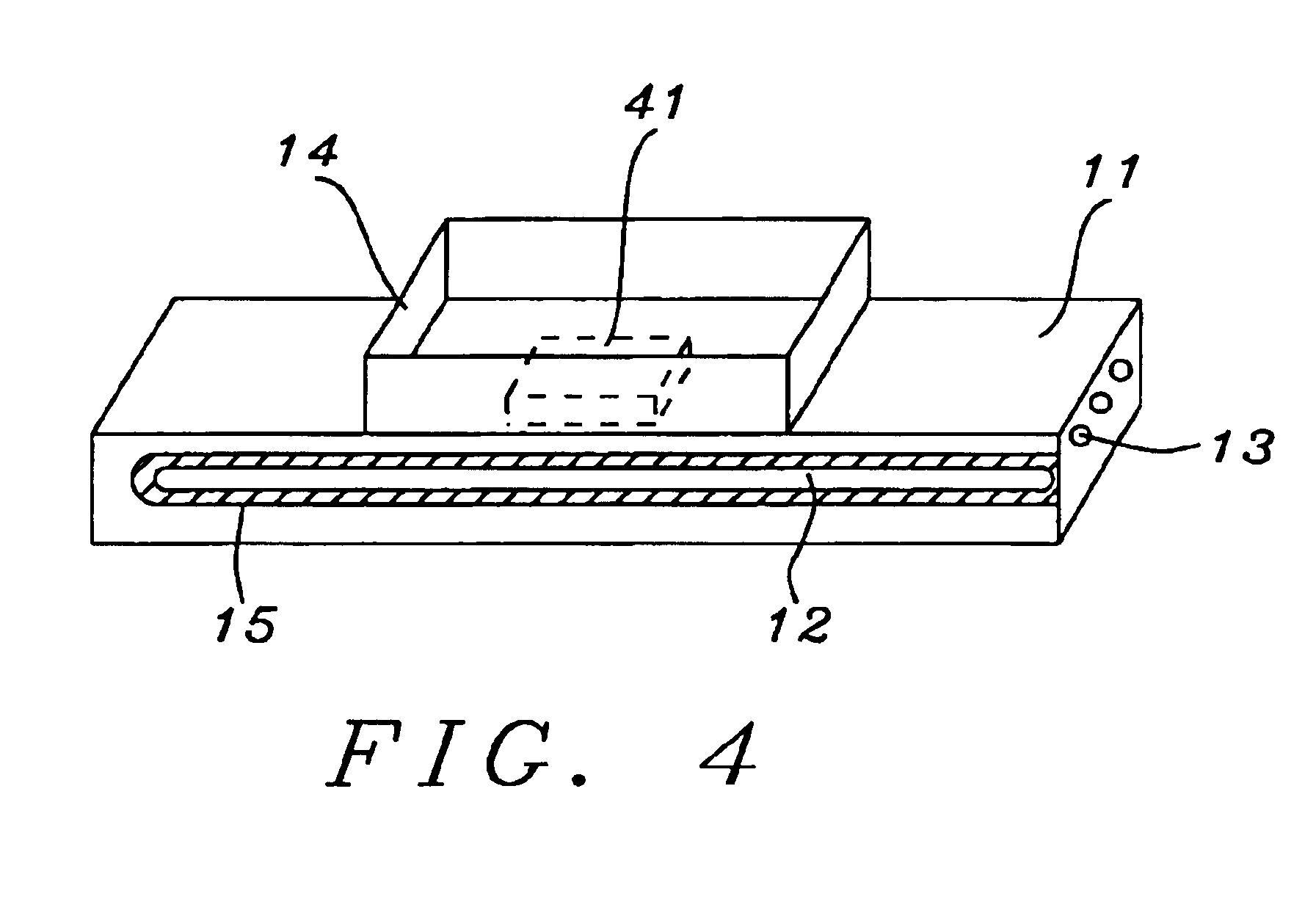
Heat dissipation during the operation of integrated circuit chips is an old problem that continues to get worse. The present invention significantly ameliorates this by placing an embedded heat pipe directly beneath the chip. Using powder injection molding, the lower portion of the package is formed first as an initial green part which includes one or more cavities. The latter are then lined with a feedstock that is designed to produce a porous material after sintering, at which time a working fluid is introduced into the porous cavities and sealed, thereby forming one or more heat pipes located directly below the chip. The latter is then sealed inside an enclosure. During operation, heat generated by the chip is efficiently transferred to points outside the enclosure. A process for manufacturing the structure is also described.

Description

[0001]This application claims the benefit of Provisional Application No. 60 / 315,306, field Aug. 28, 2001.FIELD OF THE INVENTION[0002]The invention relates to the general field of microelectronics with particular reference to packaging and heat dissipation.BACKGROUND OF THE INVENTION[0003]As the world moves towards higher performance communication and computer systems, microelectronic devices are running into basic barriers related to heat dissipation. Options under exploration include active and passive packaging designs. The active designs require fans or pumps to circulate fluids for heat extraction, often leading to heat generation, power drain, and new failure modes. The alternative is to move into passive designs, such as fins to radiate heat into the enclosure.[0004]High thermal conductivity materials are desirable for heat dissipation, and current favorites include tungsten-copper, molybdenum-copper, and aluminum or copper. The latter choices suffer from high thermal expansio...

Claims


Application Information

Patent Timeline
IPC IPC(8): H01L21/48H01L23/34H01L21/02H01L23/427B22F3/02B22F3/11B22F5/10B22F5/12B22F7/06F28D15/02H05K7/20
CPCF28D15/0275H01L21/4871H01L23/427F28D2015/0225Y10T29/49353H01L2924/0002H01L2924/00
Inventor GERMAN, RANDALL M.TAN, LYE-KINGJOHNSON, JOHN
Owner ADVANCED MATERIALS TECHNOLOGIES
Learn More