

Composite components with integral protective casings
a technology of composite components and protective casings, applied in the direction of weapons, transportation and packaging, fuselages, etc., can solve the problems of low densities of polymer composites, affecting the feasibility of using materials such as metals and metal alloys, and affecting the use of rockets, missiles and other similar airborne structures that move through the air at very high speeds
- Summary
- Abstract
- Description
- Claims
- Application Information
AI Technical Summary
Benefits of technology
Problems solved by technology
Method used
Image

Examples
example 1
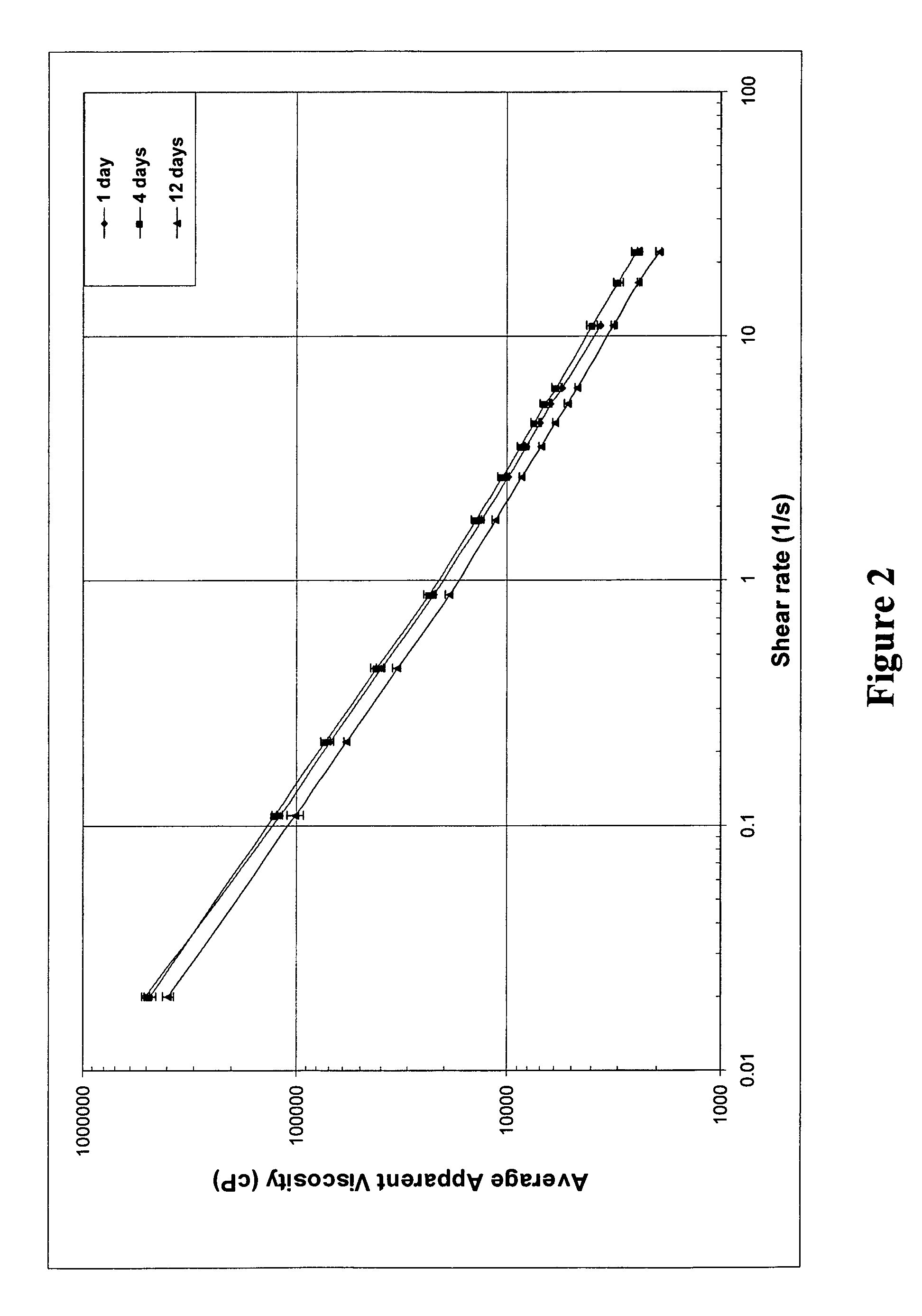
Slurry Evaluation
[0038]The following Si3N4 slurries were evaluated:[0039](1) Ceramic slurry made from a premixed blend of UBE E-5 and E-10 Si3N4 powder, commercially available from UBE Industries, Tokyo, Japan, and ceria-based sintering aids (53 vol % solids loading);[0040](2) Ceramic slurry made from a premixed blend of UBE E-5 and E-10 Si3N4 powder and added ceria-based sintering aids (50 vol % solids loading);[0041](3) Ceramic slurry of UBE E-5 and E-10 Si3N4 powder and aluminum nitride and alumina and yttria sintering aids (52.18 vol % solids loading);[0042](4) Ceramic slurry made from Stark M-11 Si3N4 powder, commercially available from H. C. Starck Inc., Newton, Mass., and alumina and yttria sintering aids, commercially available from Malakoff Industries, Malakoff, Tex., and Molycorp Inc., Mountain Pass, Calif., respectively (52 vol % solids loading);[0043](5) Ceramic slurry made from Stark M-11 Si3N4 powder and alumina and yttria sintering aids (42 vol % solids loading); and[...
example 2
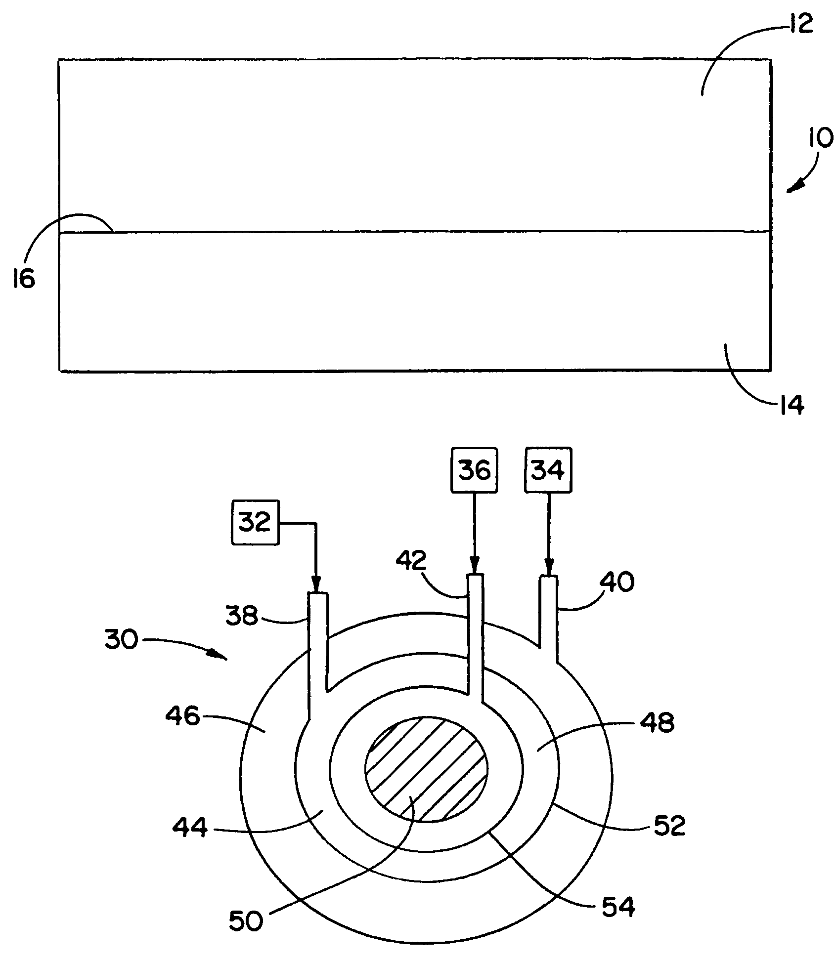
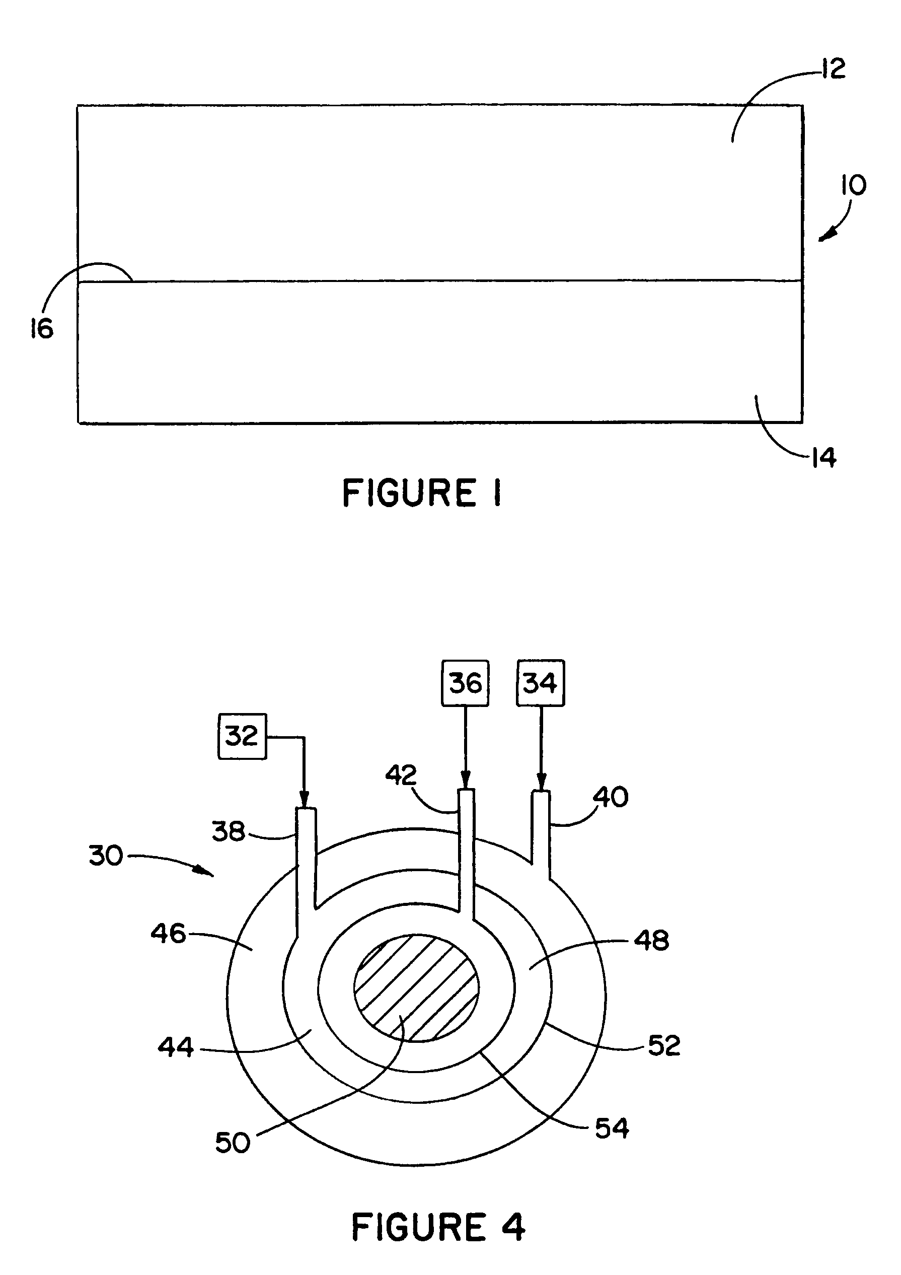
CITRM of Composite Panels with Integral Heat Shields
[0049]Composite panels were fabricated using a CIRTM process. Epoxy resin and silicon nitride ceramic slurry were co-injected into a two-dimensional, 50% by volume porous fiber preforms to produce integral composite panels. A polysulfone layer was included as an intermediate layer for the epoxy resin and ceramic slurry to diffuse into and create a strong bond between the two layers after final curing. A 24-oz. S2 glass fabric was used as the preform. Initial co-injection tests were used to evaluate slurry rheology and whether the slurries were capable of being effectively co-injected with the polymer composite resins.
[0050]Once the co-injection process was complete, the composite panels were allowed to self-cure for several hours during the exothermic portion of the curing cycle. To accelerate the final stages of the endothermic curing cycle, the panels were placed in a 350° F. oven for 2 hours. The following 6″×6″ panels were prod...
PUM
| Property | Measurement | Unit |
|---|---|---|
| Temperature | aaaaa | aaaaa |
| Diameter | aaaaa | aaaaa |
| Percent by volume | aaaaa | aaaaa |
Abstract
Description
Claims
Application Information