Direct digitally tunable microwave oscillators and filters

Inactive Publication Date: 2005-08-30
REMEC BROADBAND WIRELESS NETWORKS LLC
View PDF5 Cites 23 Cited by
  • Summary
  • Abstract
  • Description
  • Claims
  • Application Information

AI Technical Summary

Benefits of technology

[0018]In accordance with another aspect of the invention, a direct digitally controlled element for tuning to a microwave frequency is provided wherein the element comprises means for generating one or more digital signals, means for noise isolating the one or more digital signals in order to reduce the noise contained in the one or more digital signals, and means for controlling a device using the noise isolated digital binary signals, the device changing a predetermined characteristic in response to the digital signals so that the device tunes itself to a microwave frequency based on the digital signals.
[0019]In accordance with yet another aspect of the invention, a direct digitally controlled capacitor for tuning a circuit to a microwave frequency is provided wherein the capacitor comprises a control plate that deflects in resp

Problems solved by technology

However, the speed of the DSL service is limited by the fact that the data travels over long telephone twisted copper wire pairs.
However, the return channel for a cable modem is quite limited in speed by the nature of cable distribution technology.
Fiber optics offers higher access speeds than the other systems and services, but fiber does not currently reach most homes and offices and installation of new fiber is very expensive.
The option of reducing the cost of the transceiver by using a lower frequency is not always practical since it may be precluded by spectrum availability limitations so that millimeter wave transceivers are desirable, but too expensive for many applications.
An undesirable by-product of frequency synthesis is phase noise that must be kept within acceptable performance levels for a p

Method used


Image

  • Direct digitally tunable microwave oscillators and filters
  • Direct digitally tunable microwave oscillators and filters
  • Direct digitally tunable microwave oscillators and filters

Examples


Example

[0039]The invention is particularly applicable to digitally controlled oscillators and filters for use in a microwave transceiver or microwave access terminal and it is in this context that the invention will be described. It will be appreciated, however, that the device and method in accordance with the invention has greater utility, such as to other communications systems that require a tuned oscillator or filter. Before describing the invention, a typical microwave subscriber terminal that may include a digitally controlled filter or oscillator in accordance with the invention will be described.

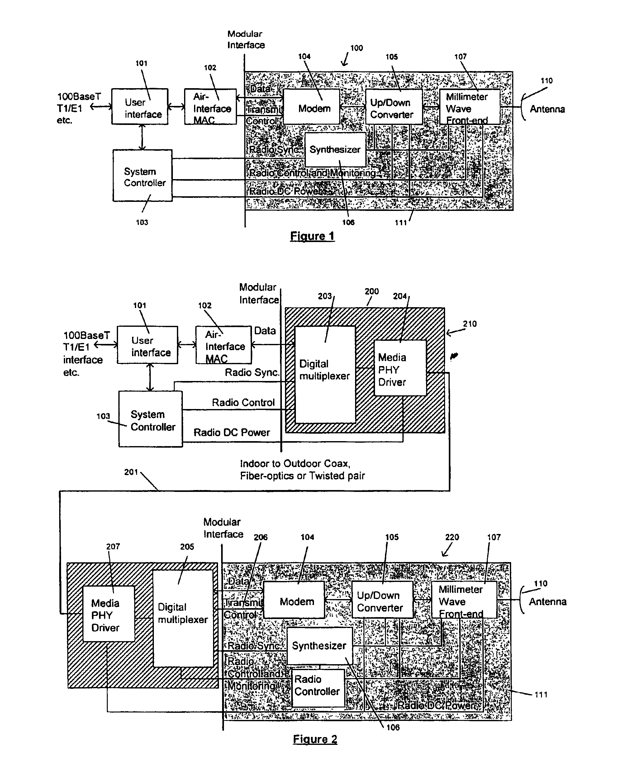
[0040]A typical digital microwave transceiver 100 for a subscriber terminal in a fixed wireless network is shown as a block diagram in FIG. 1. In particular, FIG. 1 shows an integral outdoor transceiver 100 while FIG. 2 shows a split transceiver 200, including an indoor unit 210, an outdoor unit 220 and a connecting cable 201 between them. The integral unit of FIG. 1 includes a user interf...


PUM


Abstract

A tunable element in the microwave frequency range is described that may include one or more tunable elements that are directly digitally controlled by a digital bus connecting a digital control circuit to each controlled element. In particular, each digital signal is filtered by a digital isolation technique so that the signal reaches the tunable elements with very low noise. The low noise digital signals are then converted to analog control voltages. The direct D/A conversion is accomplished by a special D/A converter which is manufactured as an integral part of a substrate. This D/A converter in accordance with the invention may consist of a resistor ladder or a directly digitally controlled capacitor. The direct digitally controlled capacitor may be a cantilevered type capacitor having multiple separate electrodes or sub-plates representing binary bits that may be used to control the capacitor. A low cost microwave oscillator is disclosed in which some of the filters and oscillators are direct digitally tuned elements.

Description

[0001]This Application is a Divisional of Ser. No. 09 / 376,867, filed Aug. 18, 1999, now U.S. Pat. No. 6,741,449.BACKGROUND OF THE INVENTION[0002]This invention relates generally to a communications device and in particular to direct digitally tunable microwave oscillators and filters that enable a low-cost high-speed digital transceiver in the millimeter wave frequency range.[0003]Telecommunication deregulation and the growth of the Internet are causing a large demand for broadband communications network access to homes and offices at increasing bit rates. For Internet access, a Digital Subscriber Loop (DSL) service and similar techniques are becoming popular. However, the speed of the DSL service is limited by the fact that the data travels over long telephone twisted copper wire pairs. Cable modems are also becoming prevalent methods of Internet and telephony access. However, the return channel for a cable modem is quite limited in speed by the nature of cable distribution technol...

Claims


Application Information

Patent Timeline
IPC IPC(8): H04B1/18H03B1/00
CPCH04B1/18H03B2201/0208H03B2201/025
Inventor PASTERNAK, ELIEZER
Owner REMEC BROADBAND WIRELESS NETWORKS LLC
Why Eureka
Try Eureka