System and method for determining the desired decoupling components for a power distribution system having a voltage regulator module

Inactive Publication Date: 2005-08-30
ORACLE INT CORP
View PDF10 Cites 41 Cited by
  • Summary
  • Abstract
  • Description
  • Claims
  • Application Information

AI Technical Summary

Benefits of technology

[0050]FIG. 10B is a schematic diagram of one embodiment of a simplified model of the voltage regulator modu

Problems solved by technology

This decrease in signal transition times (i.e., rise and fall times) creates several problems within digital electronic systems, including signal degradation due to reflections, power supply “droop”, ground “bounce”, and increased electromagnetic emissions.
Sufficient power supply droop and ground bounce can cause the device to fail to function correctly.
High frequency components present within circuits produci

Method used


Image

  • System and method for determining the desired decoupling components for a power distribution system having a voltage regulator module
  • System and method for determining the desired decoupling components for a power distribution system having a voltage regulator module
  • System and method for determining the desired decoupling components for a power distribution system having a voltage regulator module

Examples


Embodiment Construction

Incorporation by Reference

[0052]The following publications are hereby incorporated by reference in their entirety:

“Decoupling Capacitor Calculations for CMOS Circuits” by Larry D. Smith, IEEE Proceedings of the 3rd Topical Meeting on Electrical Performance of Electronic Packaging, Nov. 2, 1994; and

“Packaging and Power Distribution Design Considerations for a Sun Microsystems Desktop Workstation” by Larry D. Smith, IEEE Proceedings of the 6th Topical Meeting on Electrical Performance of Electronic Packaging, Oct. 27, 1997.

FIG. 3—Power Distribution System Model

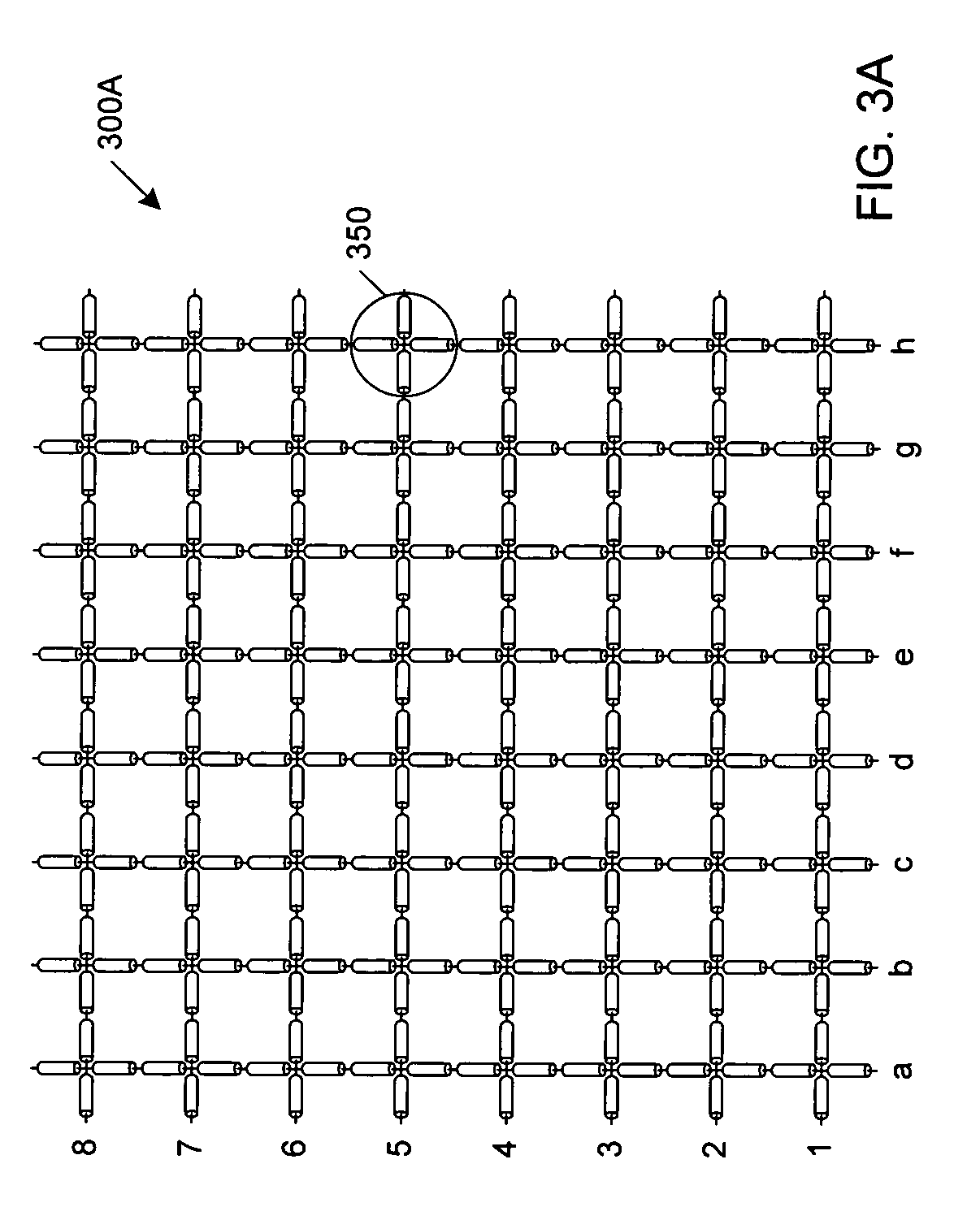
[0053]FIG. 3A is a top view of a simplified schematic of one embodiment of a model of a power distribution system. As shown, the model comprises a grid 300A of transmission line segments. The segments are grouped into unit cells 350. As shown, there are eight columns labeled “a” through “h”, as well as eight rows labeled, from the bottom to the top, “1” through “8”. The model preferably comprises a SPICE array of transmission li...


PUM


Abstract

A system and method for determining the desired decoupling components for a power distribution system having a voltage regulator module. The system may employ a mathematical model of a voltage regulator circuit, such as a switching voltage regulator. The mathematical model may be a SPICE model, or a circuit model in another format. The method may include simulating the operation of the power distribution system to obtain a estimate of the bulk capacitance required for effective decoupling. For digital systems, the method may include a cycle-by-cycle simulation of the power distribution system, wherein the simulation occurs over a number of clock cycles. The performance of the power distribution system may then be analyzed for each simulated clock cycle. The simulation may also include analyzing the transient responses and loop stability of the power distribution. Based on the results of these various simulations, the bulk capacitance value may be refined, thus allowing the system to begin the selection of specific decoupling components from the database in order to satisfy the bulk capacitance requirements.

Description

[0001]This application claims the benefit of provisional application No. 60 / 146,578 filed Jul. 30, 1999.BACKGROUND OF THE INVENTION[0002]1. Field of the Invention[0003]This invention relates to electronic systems, and more particularly to electrical interconnecting apparatus having continuous planar conductors.[0004]2. Description of the Related Art[0005]Electronic systems typically employ several different types of electrical interconnecting apparatus having planar layers of electrically conductive material (i.e., planar conductors) separated by dielectric layers. A portion of the conductive layers may be patterned to form electrically conductive signal lines or “traces”. Conductive traces in different layers (i.e., on different levels) are typically connected using contact structures formed in openings in the dielectric layers (i.e., vias). For example, integrated circuits typically have several layers of conductive traces which interconnect electronic devices formed upon and with...

Claims


Application Information

Patent Timeline
IPC IPC(8): G06F17/50
CPCG06F17/5036G06F30/367
Inventor SMITH, LARRY D.ANDERSON, RAYMOND E.ROY, TANMOY
Owner ORACLE INT CORP
Why Eureka
Try Eureka