Method of manufacturing a motor comprising a rare earth thick film magnet

a technology of rare earth and thick film, which is applied in the direction of magnetic circuits characterised by magnetic materials, magnetic bodies, evaporation applications, etc., can solve the problems of less than teen m of film thickness, less than 4 m/hr film-formation speed, and complicated method of magnet manufacturing, etc., to achieve small size, reduce a number of components, and simplify the assembly of the motor

Inactive Publication Date: 2005-09-13
PANASONIC CORP
View PDF9 Cites 6 Cited by
  • Summary
  • Abstract
  • Description
  • Claims
  • Application Information

AI Technical Summary

Benefits of technology

[0019]Also, using iron of more than 13 kG in saturated magnetization, including at least one element selected from the group consisting of nickel, cobalt, silicon, nitrogen and boron, as a substrate, a yoke of a mover of a motor can be produced at a same time when the rare ear

Problems solved by technology

Also, in the case of a multi-layer rare earth thin film magnet of 0.01-300 μm thick with the thickness of soft magnetic layer and hard magnetic layer strictly controlled at an nm level, the method of manufacturing the magnet is more complicated and less economical.
However, this method also involves problems such that the film-formation speed is less than 4 μm/hr and that the film thickness of the magnet is limited to less than teen μm.
Also, since the material is brittle and hard to process, the processing limit taking into account the yield is estimated to be about 300 to 500 μm, and it is difficult to apply to such a millimeter-sized motor as shown in FIG.
As a resul

Method used


Image

  • Method of manufacturing a motor comprising a rare earth thick film magnet
  • Method of manufacturing a motor comprising a rare earth thick film magnet
  • Method of manufacturing a motor comprising a rare earth thick film magnet

Examples


example

[0037]The present invention will be further described in detail in the following according to an example. Also it should be noted that the present invention is not limited to the example.

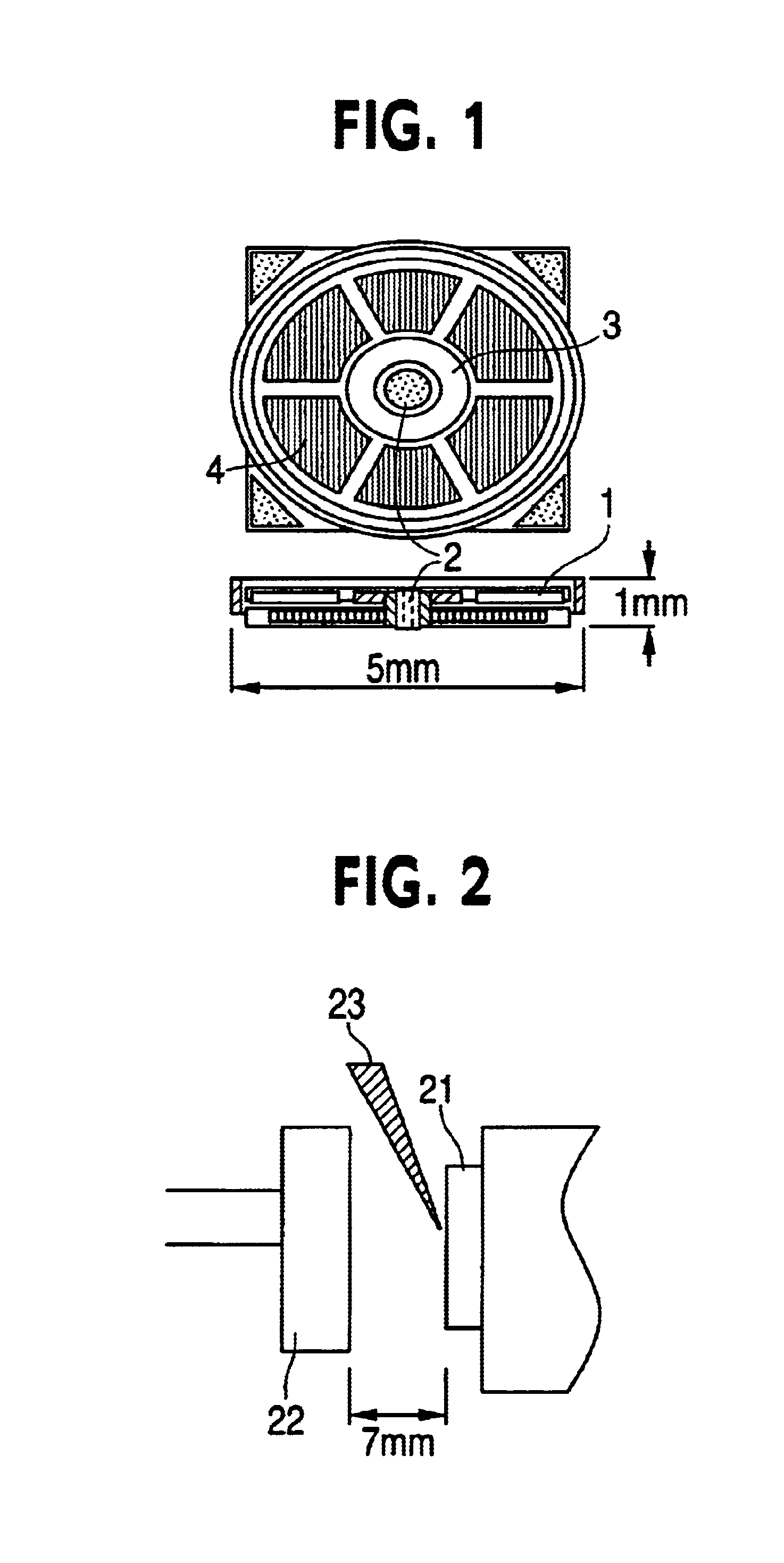
[0038]FIG. 2 is an schematic diagram illustrating an essential portion of a film-formation apparatus of the present invention.

[0039]In FIG. 2, Nd2.6Fe14B alloy is disposed as a target 21. Opposing to the target 21 a substrate made of Ta, W, Mo, SiO2, Fe, Ta, ion-inplanted Fe or the like is disposed, the substrate is 25 mm×25 mm in size and 10 μm or 100 μm in thickness. The distance between the target 21 and the substrate 22 is 7 mm.

[0040]The target 21 and the substrate 22 are disposed in a vacuum chamber, and laser beam 23 having energy of 240-340 mJ is radiated for 10-60 minutes to the target 21 under a vacuum of 5×10⁻⁷-2×10⁻⁶ Torr to form an alloy layer on the substrate 22.

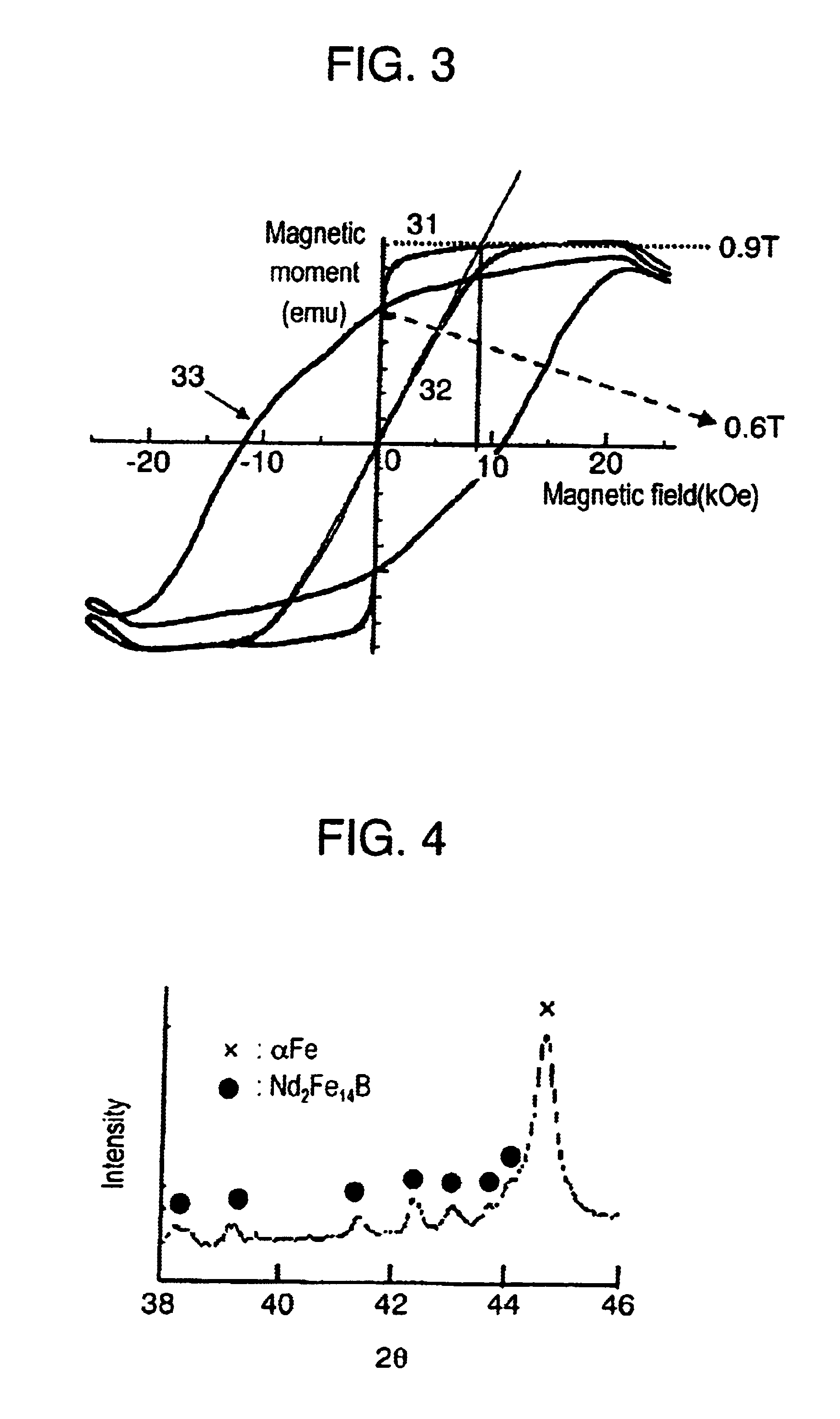
[0041]FIG. 3 shows hysteresis characteristic of a Nd2.6Fe14B alloy thick film after an one-hour film-formation on a Ta substra...


PUM

PropertyMeasurementUnit
Temperatureaaaaaaaaaa
Lengthaaaaaaaaaa
Pressureaaaaaaaaaa

Abstract

The method of manufacturing rare earth thick film magnet comprising a step of forming an alloy layer of 30-100 μm thick having a general formula RXBYTMZ on a substrate by a physical deposition process, and a step of heat-treating the alloy layer to form a thick film magnetic layer having R2TM14B phase as a main phase. In the general formula, R is at least one of rare earth elements, B is boron, TM is iron or its alloy partly substituted by cobalt. X is 0.1-0.2, Y is 0.05-0.2 and Z=1-X-Y. Further, the method of the present invention includes a step of laminating a plurality of alloy layers formed on a substrate together with the substrate. A motor comprising rare earth thick film magnet of the present invention is extremely small while obtaining high output.

Description

[0001]The instant application claims priority under 35 U.S.C. § 119 to Japanese application No. 2001-66356, filed Mar. 9, 2001.FIELD OF THE INVENTION[0002]The present invention relates to a method of manufacturing rare earth thick film magnet, and a micro-sized high-performance motor or actuator used as a driving source in the development of miro-robots, medical instruments, space crafts or the like using rare earth thick film magnet, and a method of manufacturing same.BACKGROUND OF THE INVENTION[0003]Japanese Patent Laid-Open Publication No. 05-21865 discloses a method of forming rare earth thin film magnet on a substrate such as a glass substrate, quartz substrate, and silicon wafer by a spattering method. In the Publication, a method of forming a metallic layer between the substrate or the like and the rare earth thin film magnet is disclosed. A spattering method is generally employed for forming rare earth thin film magnet.[0004]Japanese Patent Laid-Open Publication No. 06-15122...

Claims


Application Information

Patent Timeline
IPC IPC(8): H01F1/057H01F41/20H01F1/032H01F1/00H01F10/12H01F41/14H02K21/12H02K15/03H02K21/24H02K1/00H02K1/02H02K21/22H01F1/053H01F1/08C22C38/00H01F41/02
CPCH01F1/0027H01F1/057H01F10/126H01F41/205H02K21/24H02K15/03H02K1/02Y10T29/49009H02K21/22Y10T29/49012Y10T29/49078Y10T29/49075
Inventor FUKUNAGA, HIROTOSHINAKANO, MASAKIYAMASHITA, FUMITOSHI
Owner PANASONIC CORP
Why Eureka
Try Eureka