Laser annealing apparatus, TFT device and annealing method of the same

a laser annealing and tft technology, applied in the direction of identification means, instruments, therapy, etc., can solve the problems of insufficient capacity for application as a driver circuit or the like for driving a liquid crystal panel, pulse duration and change in output in terms of time, and achieve the effect of reducing or eliminating the influence of interference on the laser-irradiated area

Inactive Publication Date: 2005-09-13
PANASONIC LIQUID CRYSTAL DISPLAY CO LTD +1
View PDF19 Cites 89 Cited by
  • Summary
  • Abstract
  • Description
  • Claims
  • Application Information

AI Technical Summary

Benefits of technology

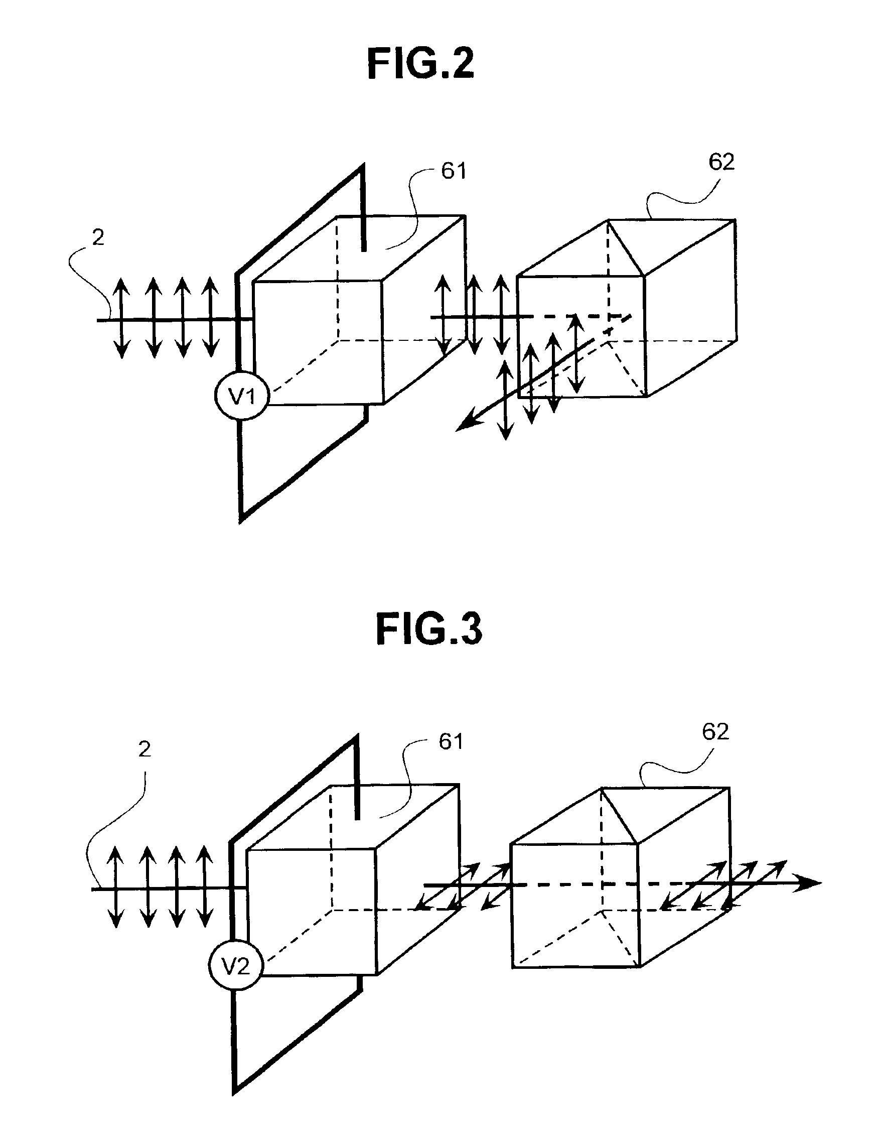
[0015]Secondly, the coherency of the laser beam having a coherency is eliminated or reduced with an incoherent optical system, and the influence of interference on the laser-irradiated area is reduced or eliminated.

Problems solved by technology

However, the pulse duration of these lasers is several dozen to several hundred nanoseconds, and the extension of the re-crystallization time is limited Specifically the crystal grain sizes attained are about one micron, and so there is still not sufficient capacity for application as a driver circuit or the like for driving a liquid crystal panel.
The first problem is that the output of the Q-switched oscillating pulse changes in terms of time in the form of a sine wave, and so a pulse duration and a change in output in terms of time, which are optimal for annealing, cannot be attained.

Method used


Image

  • Laser annealing apparatus, TFT device and annealing method of the same
  • Laser annealing apparatus, TFT device and annealing method of the same
  • Laser annealing apparatus, TFT device and annealing method of the same

Examples


Embodiment Construction

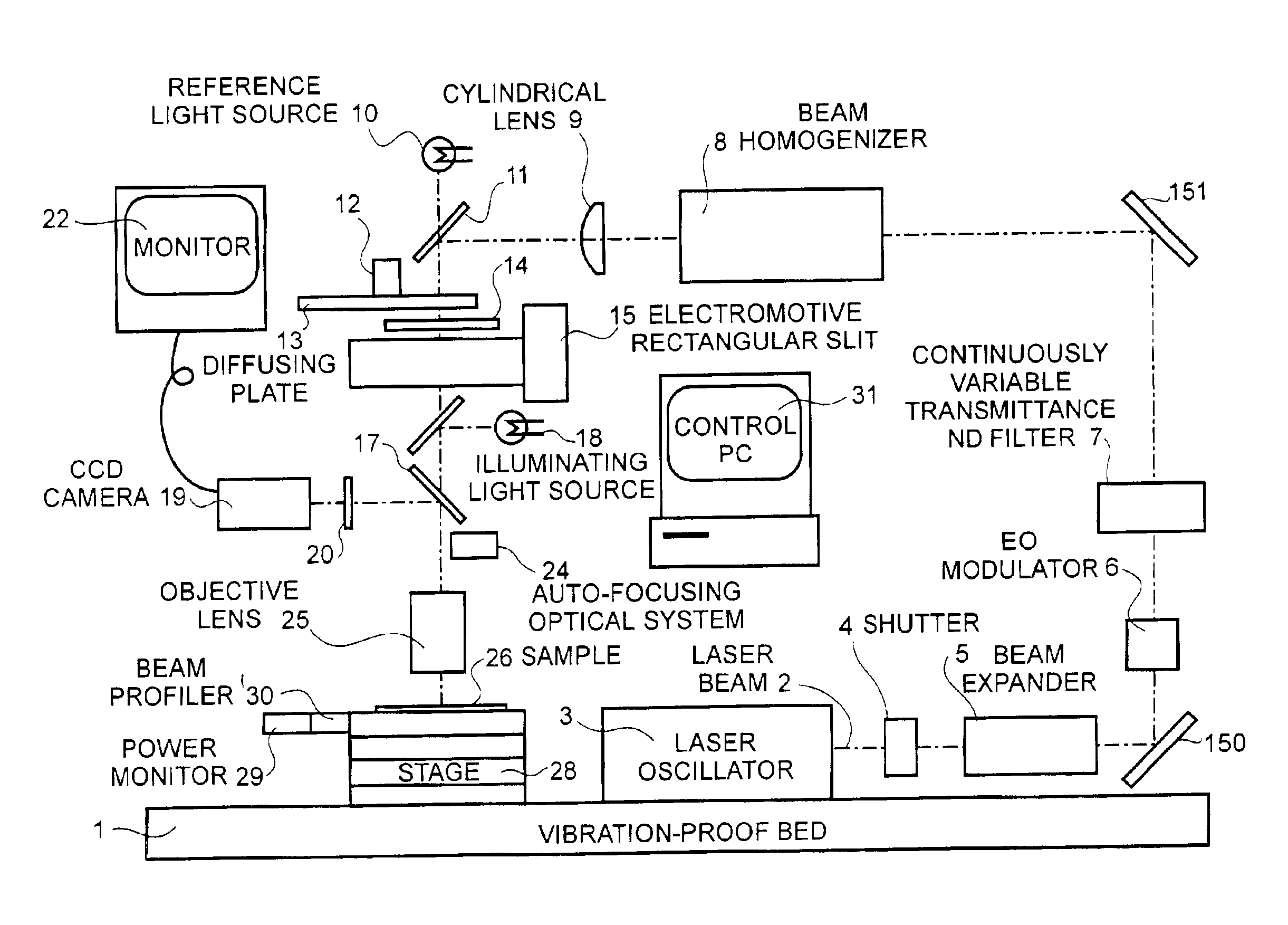
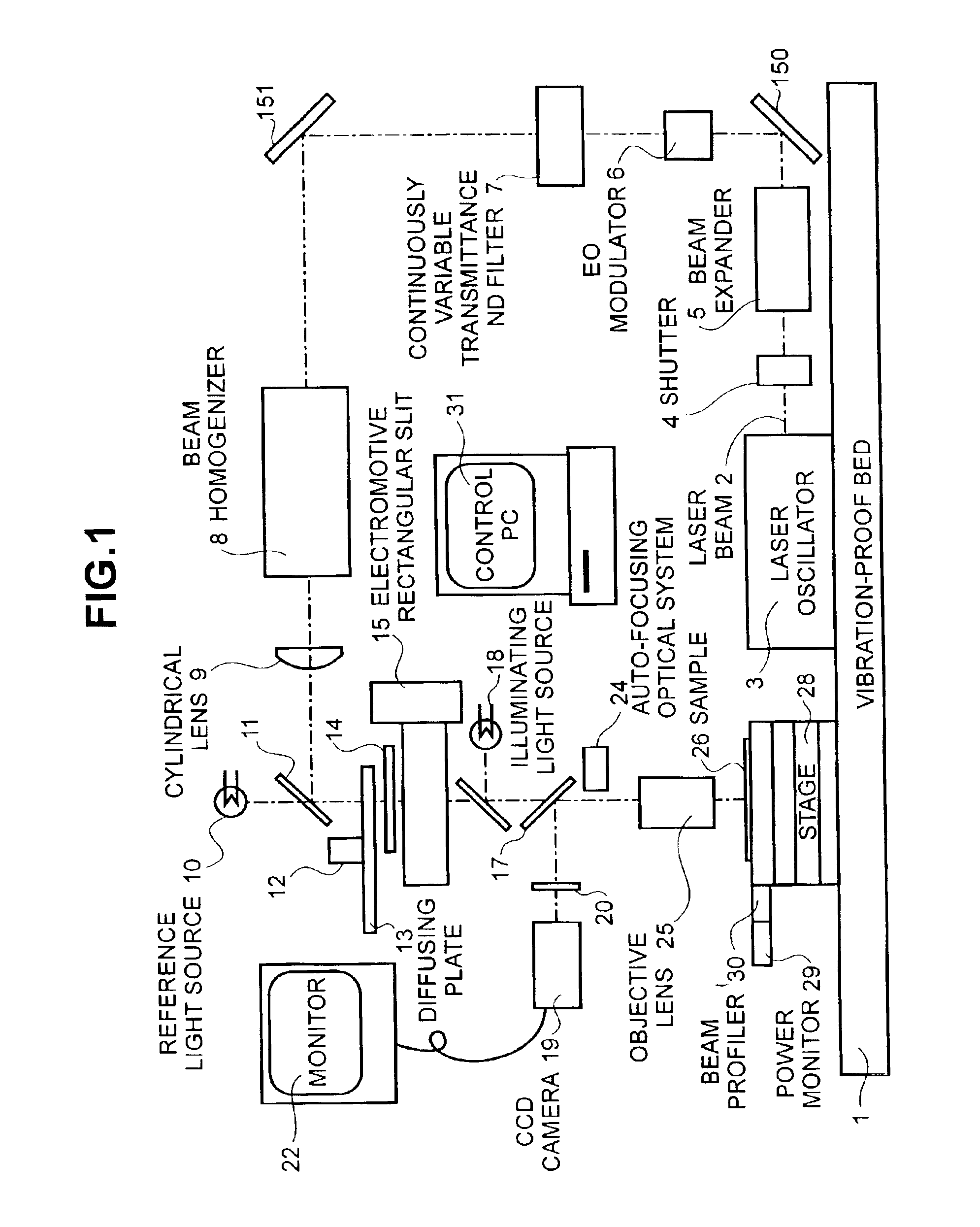
[0046]A detailed explanation of the present invention will be presented with reference to the drawings. FIG. 1 is a diagram showing the constitution of the laser annealing apparatus relating to the first embodiment of the present invention, the base of which is constituted by a bed 1, which is provided with a vibration proofing mechanism (not shown). The bed 1 serves as a support for a laser oscillator 3 for emitting a continuous wave laser beam 2, a shutter 4 for turning the laser beam 2 on and off, a beam expander 5 for expanding the beam diameter of the laser beam 2 that is output from the laser oscillator 3, an electro-optical modulator (hereinafter “EO modulator”) 6 for effecting a pulsing and temporal modulation of the energy of the laser beam 2, a continuously variable transmittance ND filter 7 for regulating the energy of the laser beam 2, a beam-homogenizer 8 for giving the laser beam 2 a uniform energy distribution, and a cylindrical lens 9 for compressing the laser beam 2...


PUM

PropertyMeasurementUnit
crystal grain sizesaaaaaaaaaa
diameteraaaaaaaaaa

Abstract

A laser beam is concentrated using an objective lens and radiated on a amorphous silicon film or polycrystalline silicon film having a grain size of one micron or less, the laser beam being processed from a continuous wave laser beam (1) to be pulsed using an EO modulator and to have arbitrary temporal energy change while pulsing ; (2) to have an arbitrary spatial energy distribution using a beam-homogenizer, filter having an arbitrary transmittance distribution, and rectangular slit; and (3) to eliminate coherency thereof using a high-speed rotating diffuser. In this manner, it is possible to realize a liquid crystal display device in which a driving circuit comprising a polycrystalline silicon film having substantially the same properties as a single crystal is incorporated in a TFT panel device.

Description

BACKGROUND OF THE INVENTION[0001]The present invention relates to a laser annealing method and laser annealing apparatus, which are capable of providing an improvement in the film qualities, the crystal grain enlargement, or single-crystallization of an amorphous or polycrystalline semiconductor film that is formed on an insulating substrate through laser beam irradiation; and, more particularly, the invention relates to a TFT device that is manufactured through laser annealing and to a display apparatus provided with such a TFT device.[0002]Currently, images are produced on liquid crystal panels by switching thin film pixel transistors that are formed with an amorphous or polycrystalline silicon film on a substrate of glass or fused quartz. Significant reductions in production costs and improvements in reliability could be expected if it were possible to form a driver circuit, for driving the pixel transistor, on the substrate at the same time.[0003]However, because the silicon fil...

Claims


Application Information

Patent Timeline
Patent Type & Authority Patents(United States)
IPC IPC(8): B23K26/073B23K26/06H01L29/66H01L21/70H01L21/02H01L29/786H01L21/336H01L21/20H01L21/268H01L27/12H01L21/84G02F1/1368G09F9/30H01L21/26H01L21/324H01L21/77H01L29/04H01S3/00
CPCB23K26/063B23K26/0639B23K26/0648B23K26/0656B23K26/0665B23K26/0732H01L21/02422H01L21/02532H01L21/02678H01L21/02683H01L21/268H01L27/1285H01L27/1296H01L29/04H01L29/66757H01L29/78675B23K26/0622B23K26/064B23K26/066H01L21/324
Inventor HONGO, MIKIOUTO, SACHIONOMOTO, MINEONAKATA, TOSHIHIKOHATANO, MUTSUKOYAMAGUCHI, SHINYAOHKURA, MAKOTO
Owner PANASONIC LIQUID CRYSTAL DISPLAY CO LTD
Why Eureka
Try Eureka