Infrared radiation source

a radiation source and infrared technology, applied in the field of infrared radiation sources, can solve the problems of molybdenum carbide, markedly lower strength in comparison with molybdenum, formation of molybdenum carbide, etc., and achieve the effect of favorable bushings

Inactive Publication Date: 2005-09-13
HERAEUS NOBLELIGHT GMBH
View PDF9 Cites 3 Cited by
  • Summary
  • Abstract
  • Description
  • Claims
  • Application Information

AI Technical Summary

Benefits of technology

[0020]It has been found to be particularly favorable for the bushings when these have surfaces large enough to be cooled by thermal radiation and convection during operation of the infrared radiation source. In particular, at very high operating temperatures of the heat conductor, it is necessary to cool the temperature at the soldered spot far enough that no melting of the metallic solder occurs, which would result in a dissolution of the contact and a consequent failure of the infrared radiation source.

Problems solved by technology

However, at high temperatures in operation of the carbon strip, a diffusion of carbon from the graphite paper into the molybdenum of the bushing takes place with this kind of contacting.
This leads to the formation of molybdenum carbide and consequently, at operating temperatures of the carbon strip substantially above 1300° C., to embrittlement or a break-up of the bushing, since molybdenum carbide has a higher electrical resistance, a different specific volume and also a markedly lower strength in comparison with molybdenum.
Furthermore, graphite paper can be arranged between the contact strips and the heat conductor, which is in direct contact with the contact strips and thus again leads to a diffusion of carbon from the graphite paper into the molybdenum and consequently to the formation of molybdenum carbide, with the problems already described above.
The impoverishment of the heat conductor in carbon leads to a point increase of resistance and a further temperature increase, having as a consequence the burn-up of the heat conductor.

Method used


Image

  • Infrared radiation source
  • Infrared radiation source
  • Infrared radiation source

Examples


Embodiment Construction

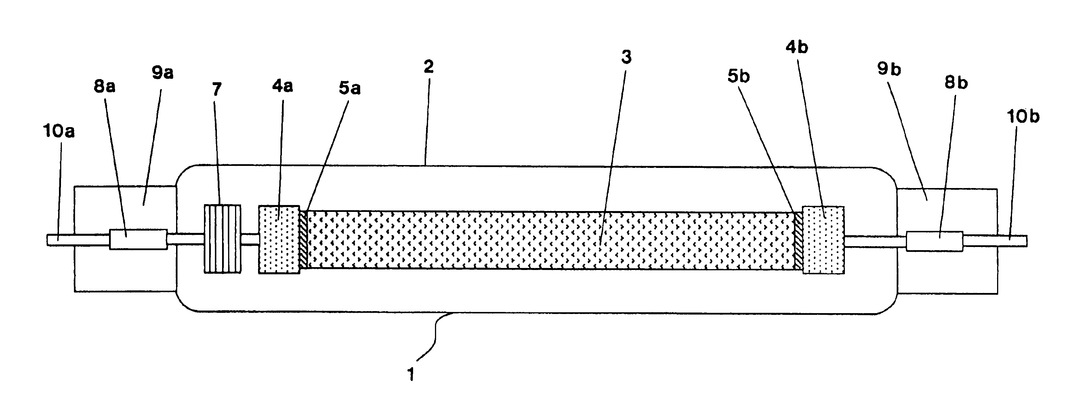
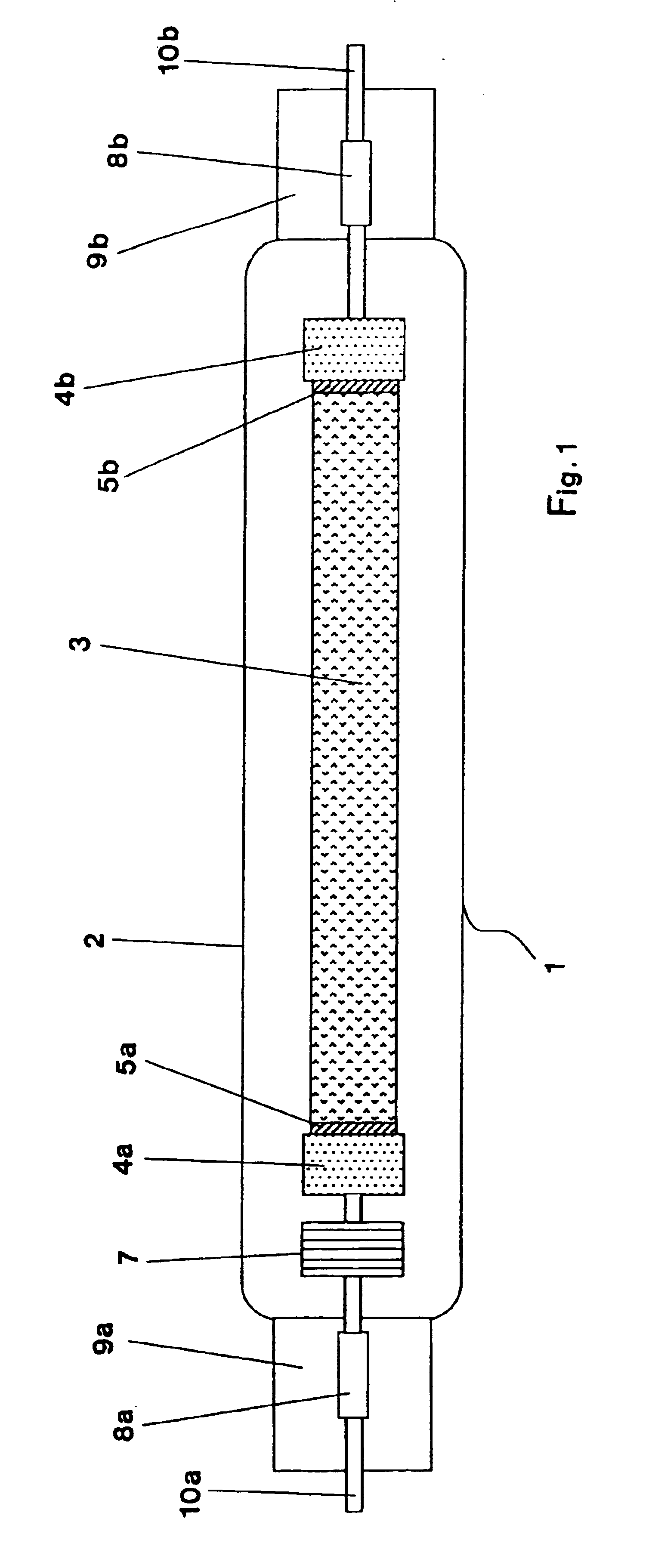
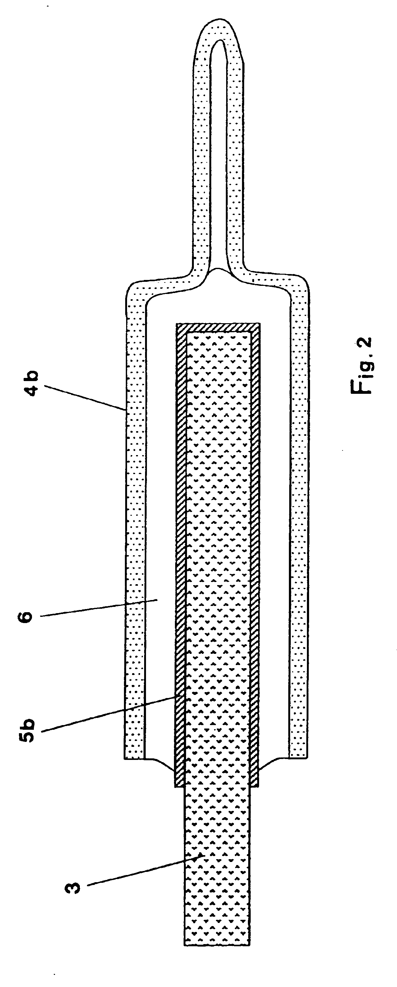
[0026]FIG. 1 shows an infrared radiation source 1 with a radiation-transparent, gas-tight tube 2 made of silica glass. A heat conductor 3 made of carbon strip is arranged inside the tube 2 and has two ends which are respectively firmly connected electrically and mechanically to bushings 4a, 4b. The two ends of the heat conductor 3 here have respective coatings 5a, 5b made of noble metal and, as can be seen in FIG. 2, are soldered to the bushings 4a, 4b with a metallic solder 6. The bushing 4a is electrically connected to a current lead-through 8a, made of molybdenum foil, by a spring element 7 for compensation of thermally caused length changes of the heat conductor 3 in operation. The current lead-through 8a is here fused gas-tight into a pinched portion 9a of the tube 2 and electrically connected to an electrical connection 10a projecting from the tube 2. The bushing 4b is directly connected electrically with a current lead-through 8b made of molybdenum foil. The current lead-thro...


PUM

PropertyMeasurementUnit
gas pressureaaaaaaaaaa
temperaturesaaaaaaaaaa

Abstract

An infrared radiation source has a radiation-transparent, gas-tight tube made of electrically insulating material, in which a heat conductor made of carbon strip is arranged. The heat conductor has two ends, which are respectively electrically and mechanically connected to bushings made of molybdenum and/or tungsten and/or tantalum, and the bushings are respectively connected via current feed-through leads with electrical connections projecting from the tube. The two ends of the heat conductor are respectively connected to one of the bushings by a metallic solder, which contains at least one of the metals titanium, zirconium or hafnium.

Description

BACKGROUND OF THE INVENTION[0001]The invention relates to an infrared radiation source (radiator) having a radiation-transparent, gas-tight tube of electrically insulating material in which is arranged a thermal conductor made of carbon strip, having two ends which are respectively electrically and mechanically connected to bushings made of molybdenum and / or tungsten and / or tantalum, wherein the bushings are respectively connected via current feed-through leads with electrical connections projecting from the tube.[0002]Such infrared radiation sources are known from German published patent application DE 100 29 437 A1. In particular, FIGS. 14 and 15 therein show the contacting between a carbon strip and a bushing made of molybdenum, the carbon strip having a coiled form and the bushing surrounding this carbon coil internally and externally. Graphite paper is arranged between the bushing and the carbon coil. A noble metal paste, or a metallic coating, for example made of nickel or a n...

Claims


Application Information

Patent Timeline
Patent Type & Authority Patents(United States)
IPC IPC(8): B32B15/01C22C16/00H05B3/00H05B3/04H05B3/02B23K35/32B23K35/24H05B3/03H01K1/06H01K1/16H01K1/20H01R4/02H05B3/10H05B3/14H05B3/44
CPCH01K1/06H01K1/16H01K1/20H05B3/009H05B3/04H05B3/145B23K35/32H05B2203/032H05B3/14
Inventor LINOW, SVEN
Owner HERAEUS NOBLELIGHT GMBH
Why Eureka
Try Eureka