All-weather energy and water production via steam-enhanced vortex tower

a technology of vortex tower and water supply, which is applied in the direction of dynamo-electric machines, sustainable buildings, energy industry, etc., can solve the problems of limited number of air turbines used before the chamber, the vortex flow is not controlled in different directions, and the chamber cannot be adaptable for direct power generation, etc., to prolong the annual operation time and ensure stability

Inactive Publication Date: 2005-09-13
KAPLOUN SOLOMON
View PDF31 Cites 55 Cited by
  • Summary
  • Abstract
  • Description
  • Claims
  • Application Information

AI Technical Summary

Benefits of technology

[0018]The steam receives kinetic energy and heat through water heating and flashing with quasi-tangential and upward acceleration of the steam jets. The vortex process intensification is going under higher decrease of pressure and faster achieving of saturation phase of humidified and swirled air. The saturation leads to the most intensive conversion of the latent vaporization heat of the involved humid air and the injected steam into kinetic energy of vortex core. The strict process control is made via inlet air vanes and different change of performance of the steam jets in different vortex zones. This way is supported by electromagnetic means of control of power generation.
[0020]The tower structure has circumferential rows of streamline columns with rows of inlet adjustable vanes between them for omnidirectional winds or sucked stagnant air. The columns and vanes form rows of flexible air nozzles sucking and accelerating the inlet flows quasi-tangentially and upward through the air openings in the vortex channel. The columns are hollow and contain a system of rows of flash-off water drums integrated with accelerating steam nozzles. The accelerated steam jets have outlets into the vortex channel between the air openings. The stable pressure decrease is forming from ambient periphery of the tower to its central axis and upward along die vortex channel, involving and helical accelerating new masses of the ambient air which carry vapor with latent vaporization heat. Average inlet velocities of sucked air can exceed the average wind velocity possible at the site from several times up to one order of magnitude and higher dependent on controlled performance of the sucking steam jets.
[0023]The higher located rows of steam nozzles create an ejection effect enhancing the electrical generator through support of the whirl of magnetic concentrators. Simultaneously these nozzles create a forcing effect for exhausting of the waste airflow through a top diffuser at the calm and insufficient winds. Thereby the steam and air nozzles located under and above the electrical generator create preferable conditions for stable operation of large-rating electrical generator over a long time. The water heating system has alternatively one or two compatible kinds of heat sources and can have regime, seasonal or off-season heat storage for starts and prolongation of annual operation time. The preferred modifications of the system, alternatively applied due to local conditions, are designed with respect to possibilities of their intensifying, compacting, and economy of auxiliary energy under vortex sucking through hot water ties.
[0027]3) Synchronous forcing and ejecting control of vortex flow before and after electrical generator via staged intake of fast steam jets, giving the highest flow capacity, stability, and minimum sizes of the tower.

Problems solved by technology

However, such vortex process can proceed interactively only at sufficient wind as a medium for energizing of vorticity.
They do not control differently the zones of vortex flow and do not adapt the chamber for direct power generation.
Moreover, the number of air turbines used before the chamber is limited by number of large assemblies moved for catching the changeable wind.
Every developed whirlwind gives low capacity that corresponds to limited capacity of the conventional turbine.
But absence of confining tower makes vortex flow unstable under any wind, reduction of air temperature or raise of air humidity.
An attempt to augment power through near-bottom heating of the air, as in U.S. Pat. No. 4,211,084, increases losses of energy and moisture into the atmosphere above the near-bottom turbine.
The similar attempts to support a confined large-scale vortex flow via artificial near-bottom swirling of the preliminary heated convection airflow face the problems of too large sizes of heating collector and chimney, large number of turbines and instability under winds and changes of atmospheric parameters.
The correspondent raised losses of purified water after these processes can not be preferred at water deficit.
The vortex tower can suck radioactive media through these ties at reactor damage.
Its combining with saturated air or vapor corrodes equipment and is chemically dangerous, as in U.S. Pat. Nos. 4,452,046 and 6,590,300.
The air heaters used inside the convection tower in U.S. Pat. No. 3,936,652 are not realistic for destroying vortex flow.
The solar heating of the air maid in the patent DE 3924968 A1 is low effective especially at peak loading because of low heat transfer to the air and absence of storage of the heated air.
They can not utilize large amount of heat augmenting power without violation of limited number of turbines or number of interconnected towers at the same site.
No one combination of the patents yields possibility to start up the vortex plant and stably generate electricity over a long time at the calm and insufficient winds.
No one combination can give large-rating electrical power from a single compact generator, adequate to excess power of the steam-enhanced tornado-type flow and comparable with attained rated power of thermal and atomic units.

Method used


Image

  • All-weather energy and water production via steam-enhanced vortex tower
  • All-weather energy and water production via steam-enhanced vortex tower
  • All-weather energy and water production via steam-enhanced vortex tower

Examples


first embodiment

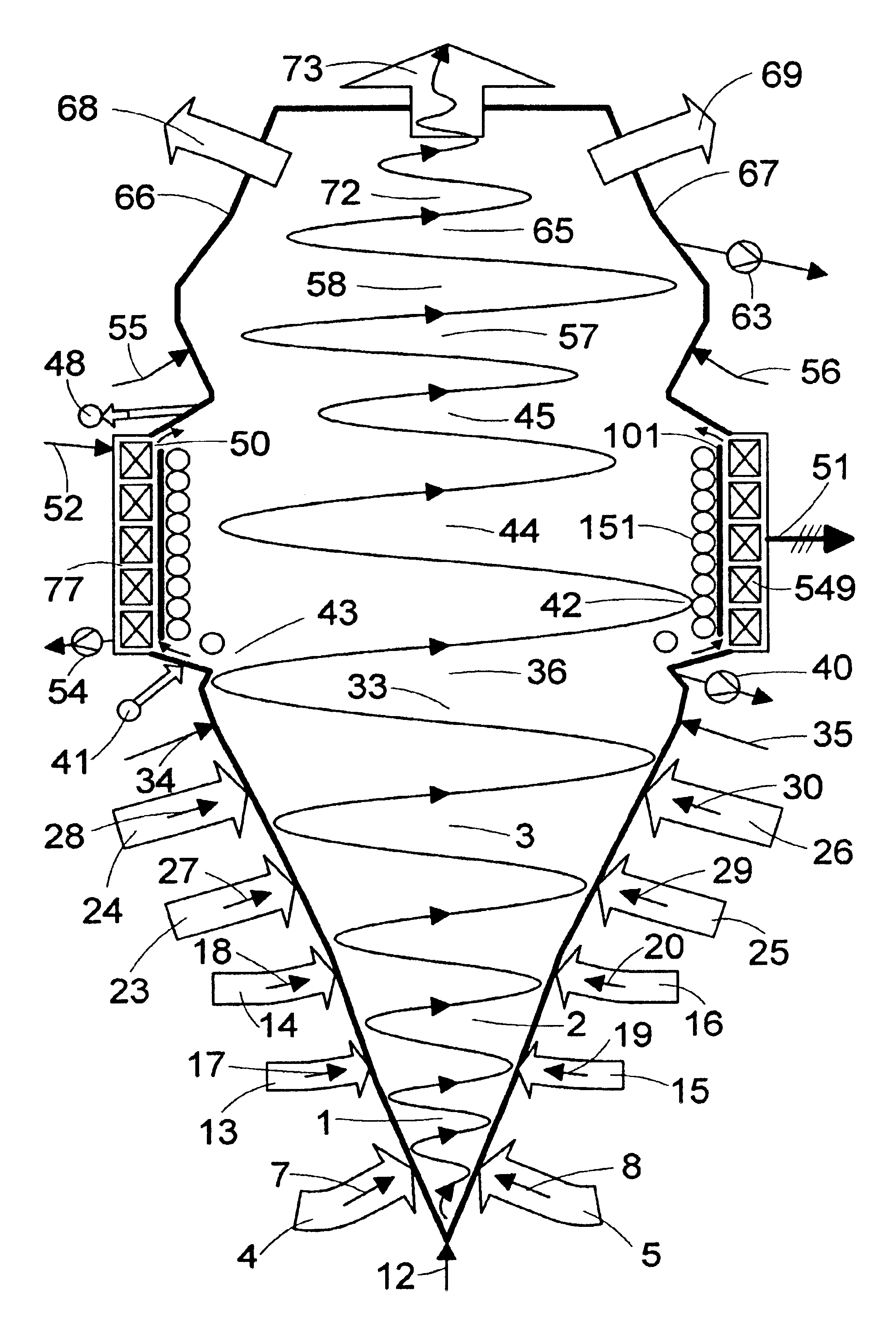
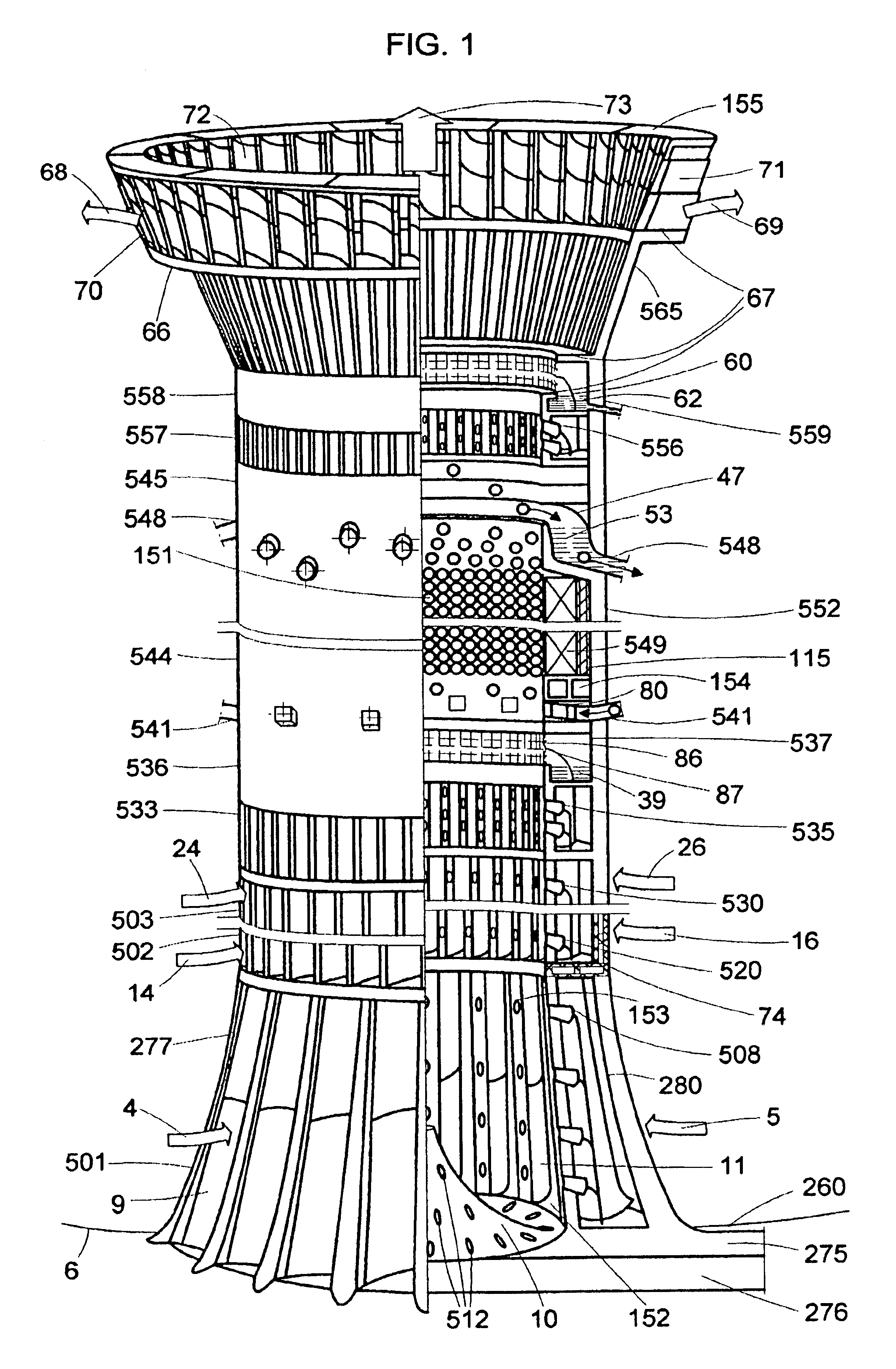
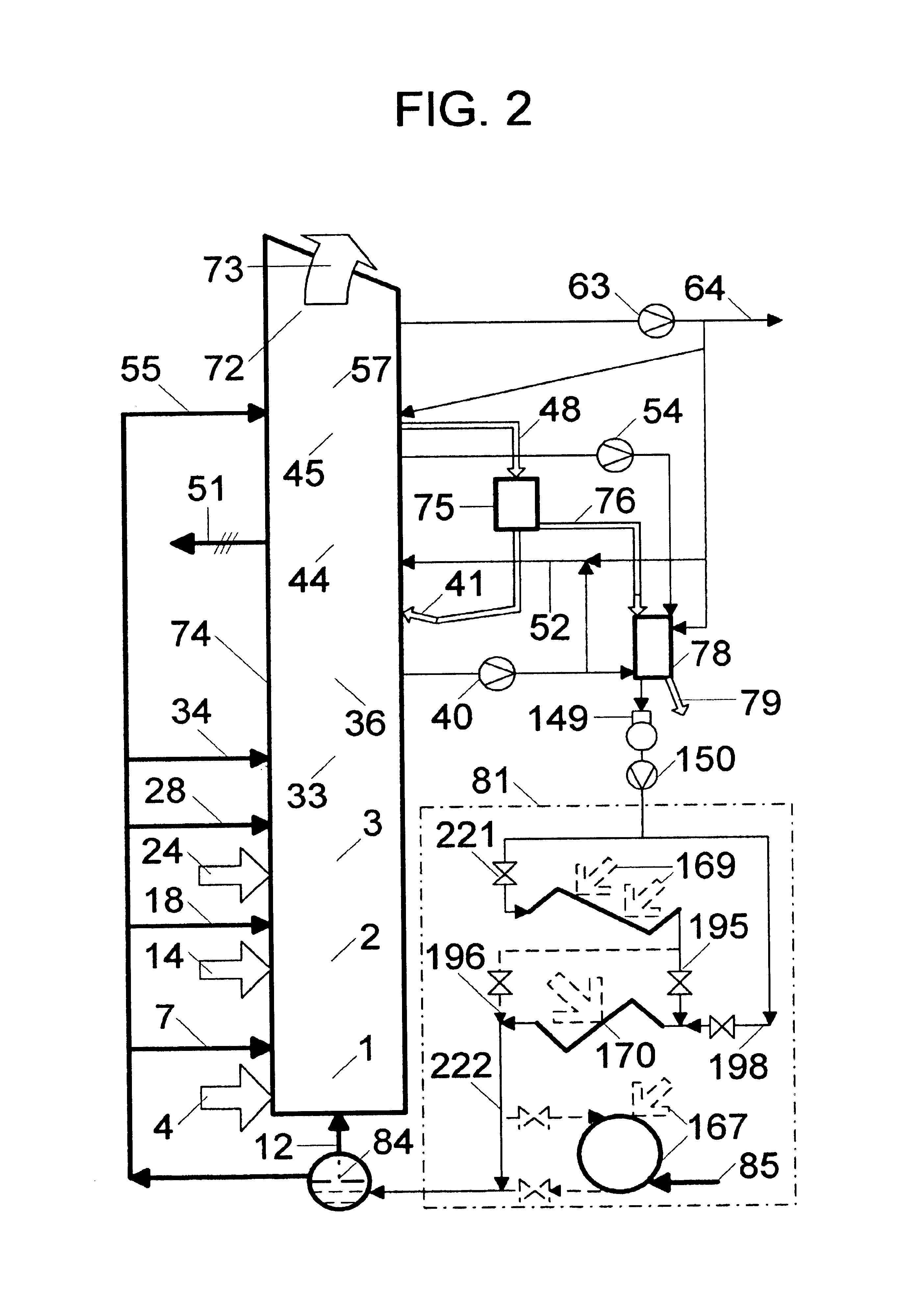
[0052]In the first embodiment the steam enhanced vortex power plant preferably comprises (FIGS. 1-4):[0053]a wind vortex tower with spatial system of circular rows of steam nozzles as 507, 508, 512, 517-520, 527-530, 534, 535 accelerating jets of saturated steam as 7, 8, 12, 17-20, 27-30, 34, 35, circular rows of inlet air nozzles accelerating airflows as 4, 5, 13-16, 23-26, a condensate separator 536, a flow-through electric generator 544 with whirled universe of magnetic concentrators as 151, and exhausting units with similar rows of steam nozzles as 555, 556 accelerating steam jets as 55, 56 and air nozzles in a re-enhancer 557, a second condensate separator 558, and a diffuser having several stages as 565; 66, 67; 70, 71; a heating system 81 giving hot water 222 to flash-off drums as 84 integrated with steam nozzles and having circulation 83. The system can have alternatively one or two compatible kinds of heat sources with regime, seasonal or off-season storage (For instance, i...

second embodiment

[0151](b) An outside zone 267, 268, 269 with barrier 266 and depression with dense coverage and fencing 272. In this invention the steam-enhanced vortex plant produces water and conditioned air, having a tower that is a simplified version of the tower described above, and comprises (FIG. 5): the energizer 501, swirlers 502, 503, re-enhances 557, separator 558, diffuser 565, and a conditioner 283 directing airflow 284 conditioned via tracks of cooler water 285, warmer water 286 and steam 287, 288 with flexible water and steam nozzles as 289, 290, 291, 292.

[0152]The conditioner 283 can turn and has adjustable retractile fins 293 directing airflow 284 according to location of conditioned landscape zone during the calm. During the winds is used an ejecting exhaust effect via a lee-side turning of an opening 294.

third embodiment

[0153]Control of the airflow 284 is made in wide ranges of ambient air parameters for favorable partial corrections of local weather via initiation or minimizing of the clouds, rains, and temperature changes. In the third embodiment the steam-enhanced vortex plant produces only water and is additionally simplified version of the simplified tower described above having diffuser with retractile vanes as 70, 71 and adjustable fins as 155 in FIGS. 1, 4.

The Process and Functioning of the Vortex Power Plant

[0154]Details of the process are disclosed with respect to main regimes of functioning such as plant starting-up, operation under power loading and switching out at the calm, insufficient and sufficient winds.

[0155]At starting-up under the calm the supplementary heat source is used directly or through storage of water heated nearly to 100° C. The flash-off drums with steam nozzles in the tower are heated up preliminary through water circulation as 83. The condensate systems and pools of...


PUM


Abstract

A wind vortex tower is enhanced by kinetic energy and heat of quasi-tangential and upward jets of saturated steam energizing, accelerating tornado-type flow and supporting stable electricity generation during the insufficient winds and calm. For action instead of absent wind at starts and operation over a long time, a staged system of flexible nozzles injects the steam jets into the zones of vortex channel. The system controls the tornado-type flow in the vorticity energizer, swirlers of sucked ambient air, condensate separators, re-enhancer of airflow and top diffuser. The steam is flashed from partially stored condensate heated nearly to 100° C. The condensate is partially delivered after centrifugal separation from saturated vortex core. The outside water heating system has one or two of compatible renewable, waste and secondary, or initial heat sources, and is intensified via sucking of heated water by vortex flow. A large-rating flow-through electric generator has an alternating magnetic whirl formed by magnetic concentrators whirled near vortex core and a three-phase stator with switched modules. The simplified towers are used for water and conditioned air production.

Description

BACKGROUND OF THE INVENTION[0001]1. Field of the Invention[0002]This invention relates to vortex power plants, and particularly to plants with tornado-type wind tower supplementary enhanced by kinetic energy and heat of staged system of steam jets utilizing water heating source for all-weather energizing of vortex flow, large-scale power generation in a single flow-through electrical generator over a long time, and water or conditioned air production.[0003]2. Description of the Prior Art[0004]The wind vortex towers offered previously utilize for power generation only kinetic energy of a secondary airflow. The airflow is sucked by a vortex flow through an opening(s) with an air turbine(s), after getting the wind into the tower through guiding and accelerating moving structures, as in U.S. Pat. Nos. 4,070,131, 4,452,562, 4,499,034, 6,016,015, 6,215,199 and 6,518,680. Various sources and ways of heat intake near bottom of the wind vortex tower also were suggested for power augmenting, ...

Claims


Application Information

Patent Timeline
Patent Type & Authority Patents(United States)
IPC IPC(8): F03B13/10F03D9/00F03B13/00H02P9/04
CPCF03D9/002H02K7/183F05B2240/132F05B2260/24Y02B10/30Y02E10/465Y02E10/725Y02B10/70F03D9/007F03D9/25F03D9/39Y02E10/46Y02E10/72Y02E10/728Y02P80/20
Inventor KAPLOUN, SOLOMON
Owner KAPLOUN SOLOMON
Why Eureka
Try Eureka