
Hybrid loop cooling of high powered devices

a technology of high-power devices and loops, applied in the direction of semiconductor devices, lighting and heating apparatus, basic electric elements, etc., can solve the problems of limited heat transport capability and heat carrying distance, heat pipe operation, and the capillary limit of a heat pipe, so as to facilitate the compact flow arrangement and reduce the probability of pump cavitation

Active Publication Date: 2005-09-27
ADVANCED COOLING TECH
View PDF12 Cites 103 Cited by
  • Summary
  • Abstract
  • Description
  • Claims
  • Application Information

AI Technical Summary

Benefits of technology

[0016]In a preferred embodiment of the invention, the evaporator porous wick is formed of bonded powders of distributed sizes. The bonded powder wick may be fabricated by sintering, brazing, or pressing the powders together, or by using an adhesive bonding material such as glass or plastic. Wicks having distributed pore sizes are more tolerant of boiling inside the wicks and can consequently handle higher heat fluxes.
[0023]In another embodiment, the liquid pump and reservoir assembly is formed integrally with the evaporator to provide a compact system. The flow channel supplying the liquid into the evaporator and the liquid artery in the evaporator porous wick form a co-axial bayonet configuration to facilitate the compact flow arrangement.

Problems solved by technology

The capillary limit of a heat pipe is reached when the maximum capillary force available in the wick is not able to overcome the total pressure drop of the liquid and vapor flows inside the heat pipe and the gravity or acceleration effects on the liquid-phase working fluid.
One shortcoming of the heat pipe is that its heat transport capability and heat carrying distance are limited by the capillary limit in the wick structure, which is sensitive to the orientation and magnitude of the gravity.
In addition, a high heat flux input at the evaporator presents another significant problem to the heat pipe operation.
The increasing heat flux may cause boiling inside the wick structure in the evaporator portion of the heat pipe, disrupting the returning liquid flow and consequently causing dry-out in the evaporator.
The reduced liquid pressure drop results in an increase in the liquid flow rate and consequently in heat transport capability and heat carrying distance.
However, these arteries are susceptible to boiling at high heat flux conditions, wherein the resultant vapor bubbles can interrupt or block the capillary driven liquid flow through the arteries, resulting in system failures.
Loop heat pipes and capillary pumped loops have very limited capabilities of handling high heat flux input.
The resultant vapor superheating substantially reduces the heat transfer efficiency and limits the heat flux capacity of the loop heat pipe and capillary pumped loop.
In either scenario, however, the inability to precisely regulate liquid flow to the evaporator can result in an excess liquid supply to the evaporator, also known as “flooding,” which results in decreased heat transfer performance.
In addition, spray cooling systems are generally prone to clogging in the nozzles, and their performance may be sensitive to gravity and acceleration.
The complexity of the control system results in increased system cost, size and weight, and decreased system reliability and endurance.

Method used


Image

  • Hybrid loop cooling of high powered devices
  • Hybrid loop cooling of high powered devices
  • Hybrid loop cooling of high powered devices

Examples


Embodiment Construction

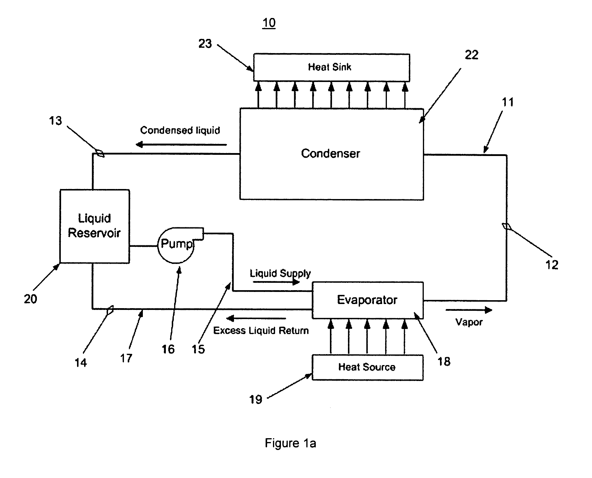
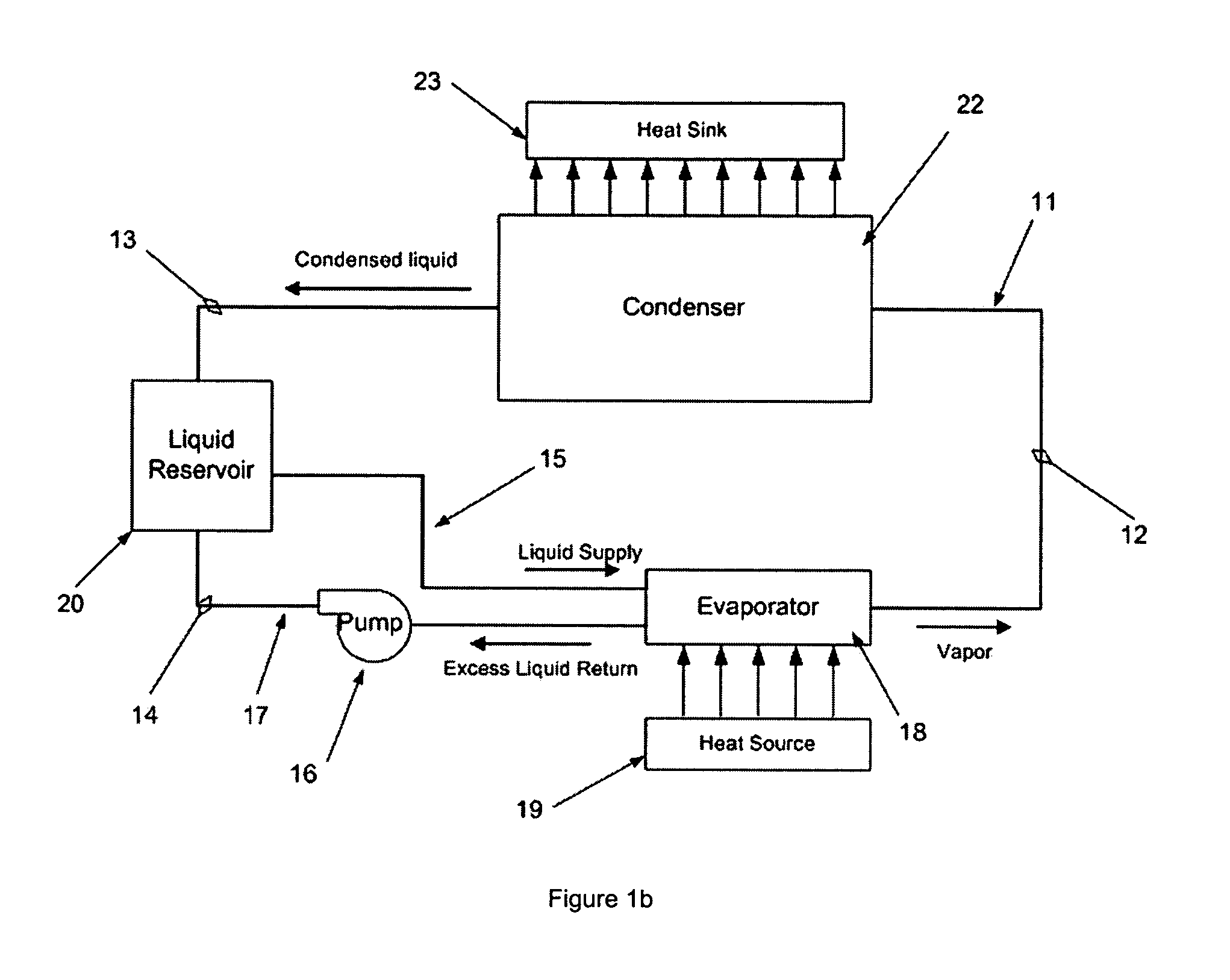
[0043]As used herein, the term “hybrid loop” refers to the heat transfer loop system that includes a primary passive two-phase flow segment and a secondary actively pumped liquid flow segment. The terms “bonded powder”, “powder wick” and “porous wick” refer to any means of bonding metal, ceramic, glass or plastic powder or fiber materials together to form a porous wick structure, including, but not limited to, sintering, diffusion bonding, hot pressing, brazing, soldering, and bonding with plastic or glass. The term “condenser” means a portion of a two-phase device or a discrete component connected thereto, in which a vapor-phase working fluid condenses to liquid-phase as the latent heat of vaporization is transferred to an associated heat sink. The term “evaporator” means a portion of a two-phase device or a discrete component connected thereto, in which evaporation of a liquid-phase working fluid occurs as the fluid absorbs heat from an associated heat source.

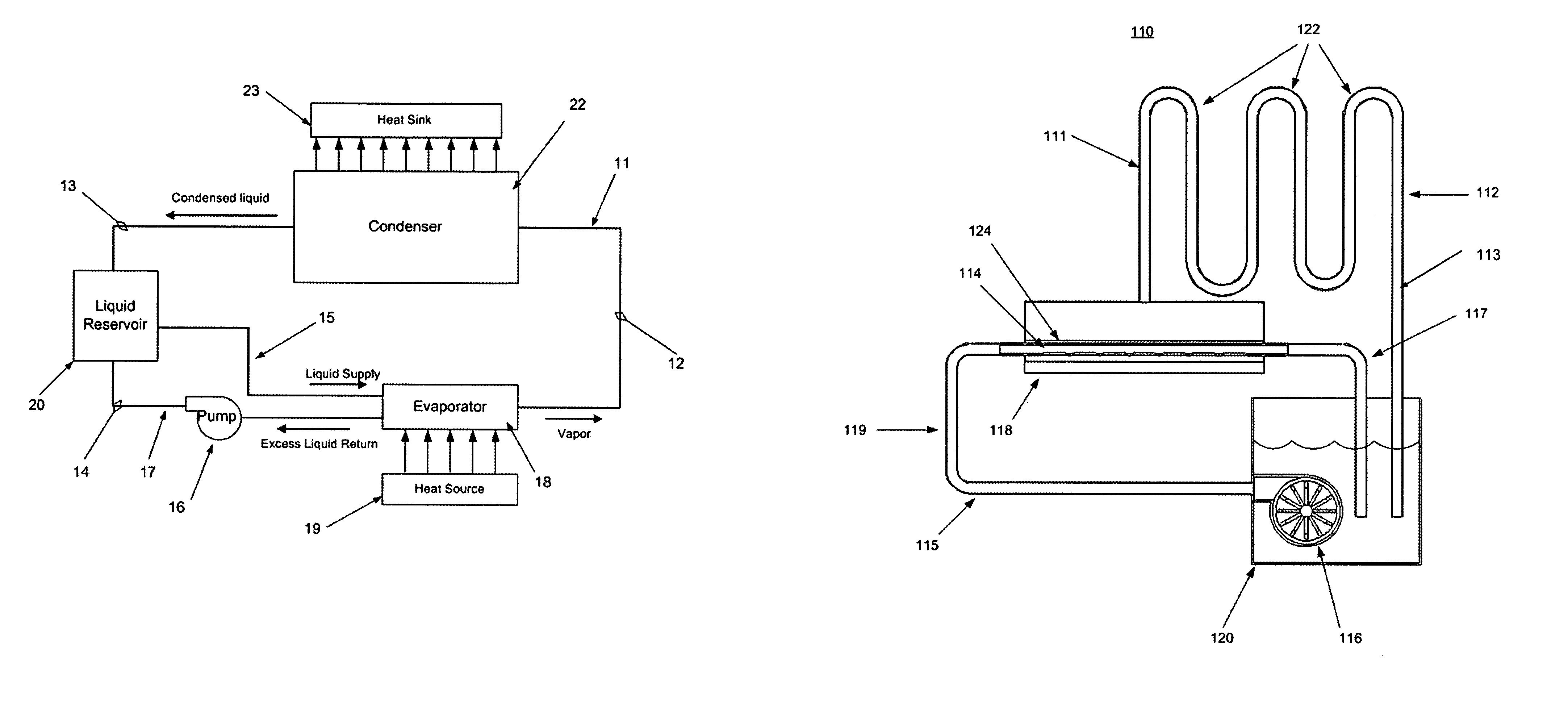
[0044]FIG. 1a illustr...


PUM


Abstract

A heat transfer loop system includes a primary passive two-phase flow segment with an evaporator, a condenser and a liquid reservoir, and a secondary actively pumped liquid flow segment in which the liquid in the reservoir is drawn by a liquid pump into the evaporator, where a portion of the liquid is vaporized by the heat input and moves into the primary segment while the excess liquid is pumped back to the reservoir. The evaporator consists of a porous wick and one or more liquid arteries encased in the porous wick. The liquid arteries have porous walls to allow liquid phase working fluid to flow into the surrounding porous wick. The liquid arteries have porous walls to allow liquid phase working fluid to flow into the surrounding porous wick. The excess liquid continues to move through the arteries and eventually out of the evaporator and into the reservoir. The porous wick provides sufficient capillary force to separate the liquid inside the arteries and the vapor in the evaporator.

Description

BACKGROUND OF THE INVENTION[0001]1. Field of the Invention[0002]The present invention relates to heat transfer devices, and more particularly, to a hybrid heat transfer loop system that consists of both capillary driven two-phase flow and actively pumped liquid flow segments.[0003]2. Description of Prior Art[0004]Attaching a heat pipe to a waste heat generating component such as an integrated circuit is a known and successful technique of moving the undesired waste heat away from that electronic component. One portion of the heat pipe is exposed to the heat source and another portion of the heat pipe is exposed to a heat sink, which is at a lower temperature than the heat source. Heat is absorbed from the heat source by evaporation of a liquid-phase working fluid inside the heat pipe at the portion exposed to the heat source (the evaporator). The vapor phase working fluid with its absorbed heat load (latent heat of vaporization) is thermodynamically driven to the portion of the heat...

Claims


Application Information

Patent Timeline
Patent Type & Authority Patents(United States)
IPC IPC(8): F28D15/04F28D15/02H01L23/427
CPCF28D15/0266F28D15/043F28D15/046H01L23/427H01L2924/09701H01L2924/0002H01L2924/00
Inventor ANDERSON, WILLIAM G.EASTMAN, G. YALESARRAF, DAVID B.ZUO, JON
Owner ADVANCED COOLING TECH
Learn More