Mask shaping using temporal and spatial coherence in ultra high resolution lithography

a technology of temporal and spatial coherence and applied in the field of microlithography, can solve problems such as difficulty, achieve the effects of reducing ripple and bright spots, improving the printing of two-dimensional patterns by ultra high resolution lithography, and reducing or eliminating ripple and bright spots

Inactive Publication Date: 2005-10-11
BOURDILLON ANTONY J
View PDF2 Cites 8 Cited by
  • Summary
  • Abstract
  • Description
  • Claims
  • Application Information

AI Technical Summary

Benefits of technology

[0015]It is a second object of the invention to reduce, by temporal and spatial coherence, the amplitude of Ripple in the Fresnel patterns used in the exposures.
[0017]It is a fourth object of the invention to adjust the intensities in aerial images of basic shapes so as to provide, on development, squarer corners, and straighter edges.
[0024]In accordance with the present invention, the printing of two-dimensional patterns by Ultra high Resolution Lithography is improved by using masks shaped for temporal and spatial coherence. The invention overcomes a difficulty, or shortcoming in Ultra High Resolution Lithography, of printing two dimensional structures. The difficulty occurs especially where the structures are asymmetrical. Following the principles of the coherence and with an optimization of bandwidth, the invention employs simulations or paradigms of mask shapes to print near-ideal patterns. By these methods Ripple and Bright Spots are reduced or eliminated. By the methods described, exposure times and throughput are optimized, consistent with a required resolution in printing.

Problems solved by technology

The difficulty occurs especially where the structures are asymmetrical.

Method used


Image

  • Mask shaping using temporal and spatial coherence in ultra high resolution lithography
  • Mask shaping using temporal and spatial coherence in ultra high resolution lithography
  • Mask shaping using temporal and spatial coherence in ultra high resolution lithography

Examples


main embodiment

Operation—Main Embodiment

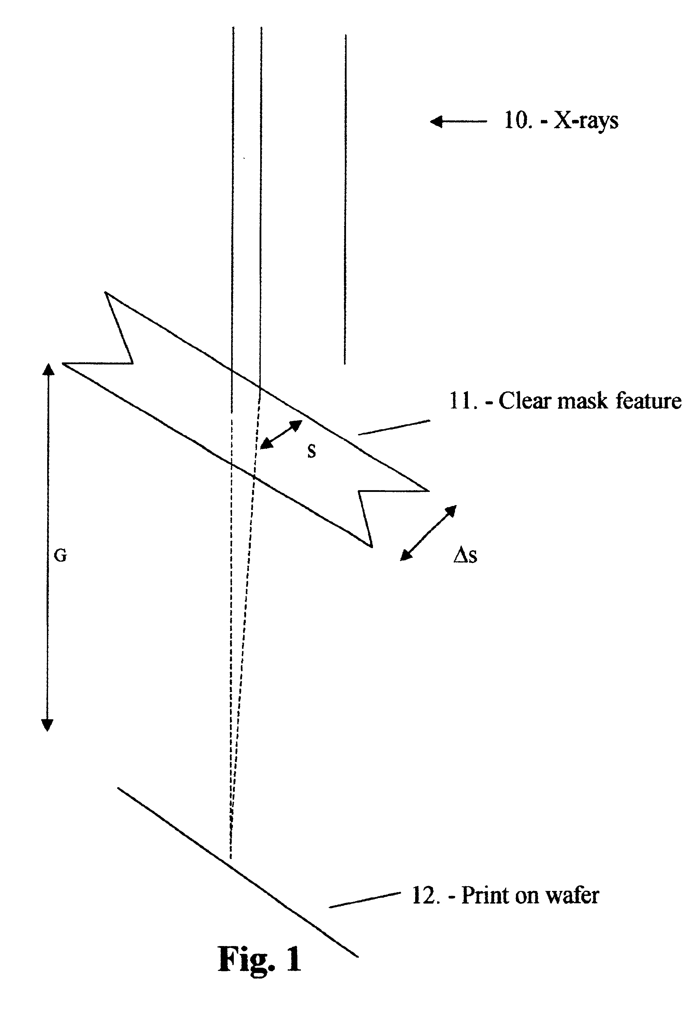
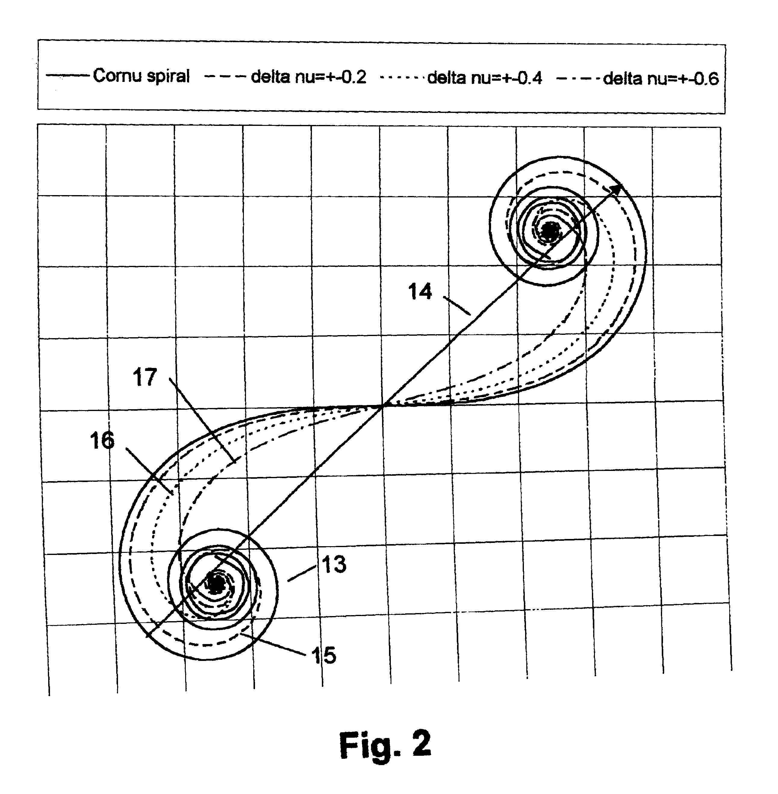
[0079]Typically, Ultra High Resolution Lithography printing is employed at or near the Critical Condition by the appropriate setting of the mask-wafer gap. The dimensionless spatial co-ordinate will then be Δν=2.4. For the printing of two dimensional patterns, the Critical Condition is typically set for the shorter pattern dimension.

[0080]Typically, 0.8 nm (1.5 kV) X-rays are used in the illumination within the dimensionless range Δν=2.4±0.2, corresponding to a photon wavelength range 0.55<λ<1.1 nm (or energy range 1<ε<2 kV). The Critical Condition is set, by gap and (smallest) mask feature size, at the mean value of the range. Typically a synchrotron X-ray source is used.

[0081]Typically, the masks are made by conventional means. The masks consist, typically, of either a gold absorber on a transmitting silicon nitride substrate or of a tantalum compound absorber on a transmitting silicon carbide substrate.

[0082]Typically, a V-shaped indent is fabricated, dur...


PUM

PropertyMeasurementUnit
acute angleaaaaaaaaaa
angleaaaaaaaaaa
angleaaaaaaaaaa

Abstract

Mask Shaping using temporal and spatial Coherence for Ultra High Resolution Lithographic imaging and printing refers to methods and apparatus that can be adopted to print near-ideal images of basic shapes when the shapes are asymmetrical. Ultra High Resolution Lithography refers to proximity printing of clear mask fetures when they are demagnified by bias. In this lithography, optical components, including lenses and mirrors, are not used between the mask and wafer. When a clear mask feature is asymmetric and the mask-wafer gap is set so that the Critical Condition is maintained for the shortest print dimension, then undesirable features typically appear in other longer dimensions consistent with Fresnel diffraction. The undesirable featurs impede illumination uniformity for controlled printing in exposed areas. Such features, including Bright Spots and Ripple, are counteracted by the Mask Shaping that is designed to optimize printing with temporal and spatial coherence near the Critical Condition. Even with broad band illumination, ultra high resolution is not lost. On the contrary, with Mask Shaping near the Critical Condition, the undesirable features occurring parallel to the longer dimensions, are normally reduced or eliminated. Near-ideal shapes can be printed. With Mask Shaping for temporal and spatial coherence, production parameters, including resolution, exposure time, and illumination band width can be enhanced, traded, and optimized.

Description

CROSS-REFERENCE TO RELATED APPLICATIONS[0001]Not applicable.STATEMENT REGARDING FEDERALLY SPONSORED RESEARCH AND DEVELOPMENT[0002]Not applicableBACKGROUND[0003]1. Field of the Invention[0004]This invention applies to micro-lithography and the application of micro-lithography as a tool in the development and production of micro-electronic and micro-mechanical devices and of integrated circuits.[0005]2. Description of Prior ArtBackground.[0006]Ultra High Resolution Lithography has many advantages but one significant shortcoming when it is used for printing asymmetric, two-dimensional patterns.[0007]The printing is achieved by demagnifying clear mask features without the use of either lenses or mirrors between a mask and a resist. The resist is coated onto a wafer and the mask is placed in proximity to the wafer, separated by a precise gap. The demagnification results from the positive use of two-sided bias in Ultra High Resolution Lithography. Typically, X-rays are used for exposing t...

Claims


Application Information

Patent Timeline
Patent Type & Authority Patents(United States)
IPC IPC(8): G03F7/20G03F1/14G03F1/22G03F1/36
CPCG03F1/22G03F7/70216G03F7/70325G03F7/7035G03F1/36Y10S430/143
Inventor BOURDILLON, ANTONY J
Owner BOURDILLON ANTONY J
Why Eureka
Try Eureka