Mass spectrometry methods using electron capture by ions

a mass spectrometry and electron capture technology, applied in the field of ion fragmentation techniques, can solve the problems of erroneous structure assignment, loss of information on location, and collisional and infrared dissociation techniques have serious drawbacks, and achieve the effect of effective electron capture dissociation

Inactive Publication Date: 2005-10-25
ZUBAREV ROMAN A
View PDF7 Cites 8 Cited by
  • Summary
  • Abstract
  • Description
  • Claims
  • Application Information

AI Technical Summary

Benefits of technology

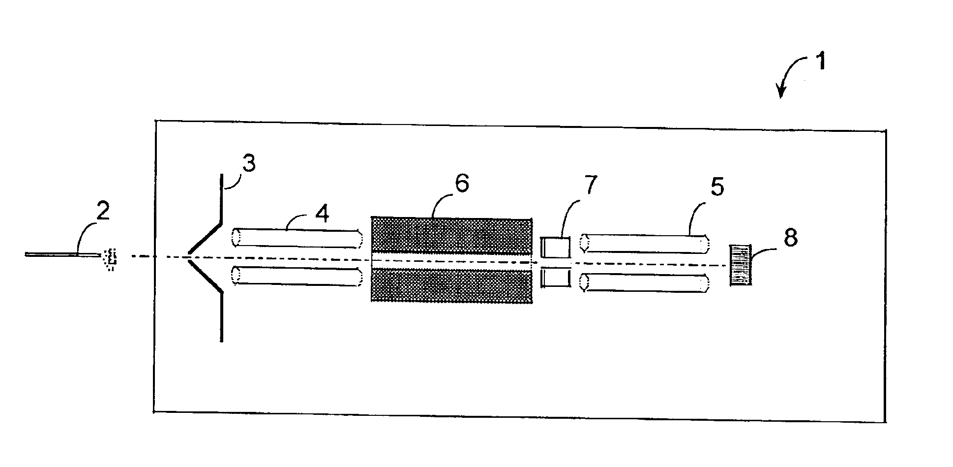
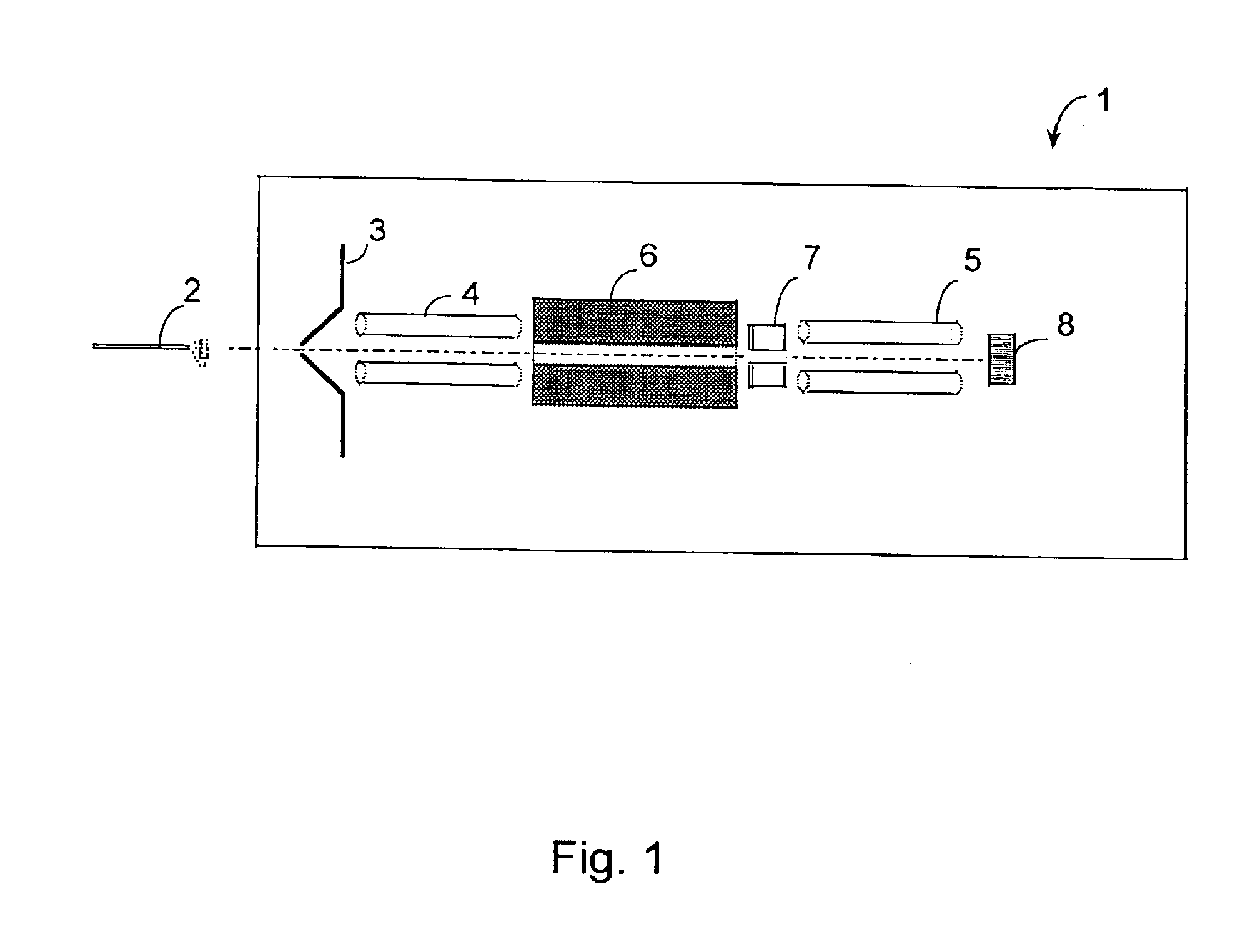
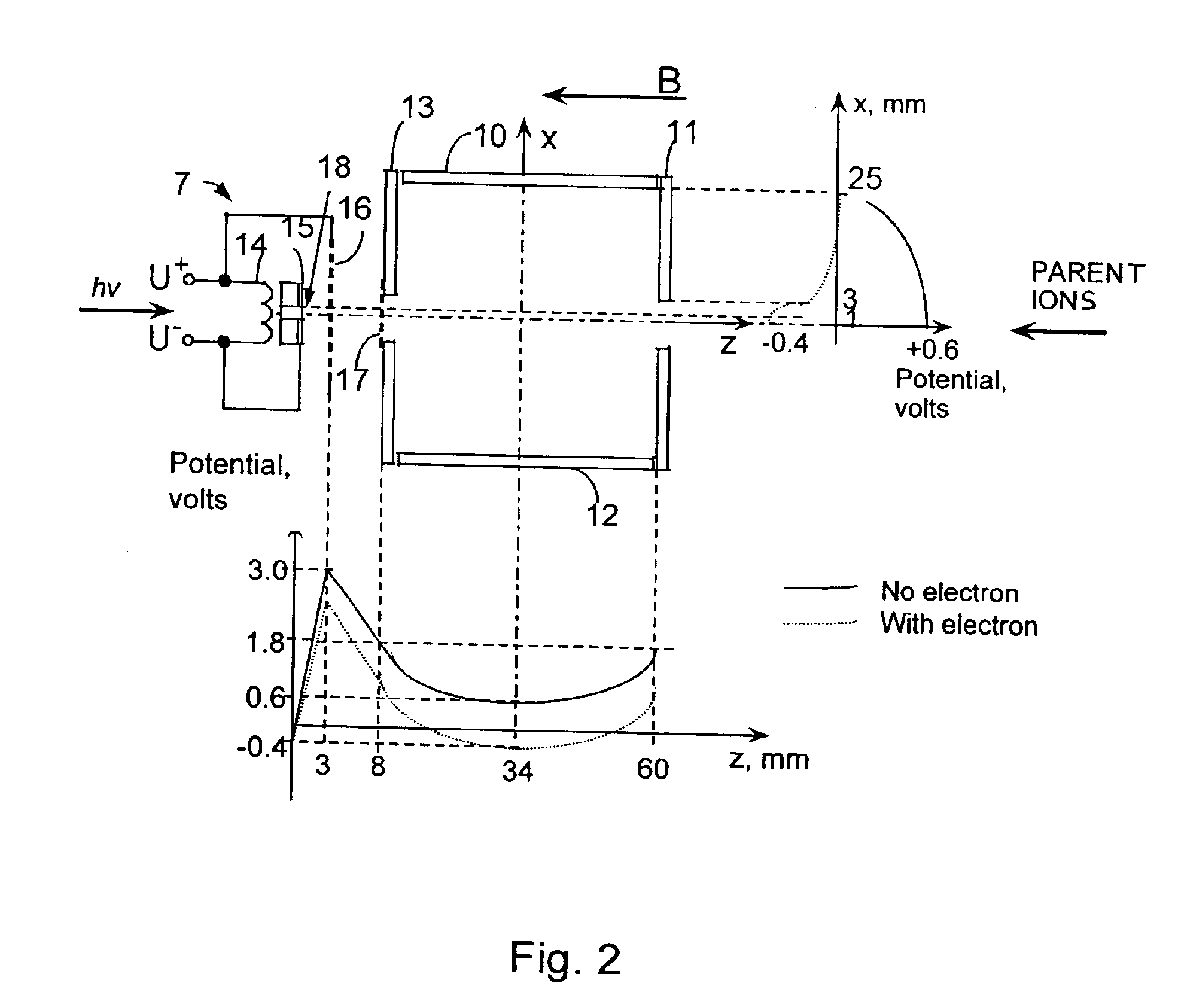
[0013]According to the present invention, methods are provided for producing effective electron capture dissociation of positive ions in tandem mass spectrometry. A high-flux, broad electron beam is used that traverses essentially the full width of a region occupied by parent ions for at least a period of time. The beam produces potential depression along its axis, that is at least as large as the kinetic energy of motion of ions radially to the beam axis. The ions thus become trapped within the volume occupied by the electron beam during the time of electron irradiation, thereby offering effective capture by the ions of low-energy electrons present in the beam. The fragment ions formed as a result of the electron capture will also be trapped inside the beam, which results in their effective collection.

Problems solved by technology

Both collisional and infrared dissociation techniques have serious drawbacks.
Firstly, increase of the internal temperature causes intramolecular rearrangements that can lead to erroneous structure assignment, as discussed in Vachet, Bishop, Erickson and Glish, (1997) Am. Chem. Soc.
Secondly, low-energy channels of fragmentation dominate, which can limit the multiplicity of cleaved bonds and thus the fragmentation-derived information, and in case of the presence of easily detachable groups result in the loss of information on their location.
Finally, both collisional and infrared dissociations become ineffective for large molecular masses.
The method suffers though from low efficiency, with a maximum efficiency of total fragmentation of parent ions of about 5%.
The drawback of current electron capture dissociation methods lies in their relatively low efficiency, which manifests in the long time of electron irradiation.
The higher currents are not found to provide more efficient ECD.
In electrospray ionisation, sample ions are produced continuously and only a small fraction of these ions can be analysed in ECD experiments due to the poor duty cycle, resulting in low sensitivity.
In addition, electron capture dissociation is an energetic process, resulting in scattering of the fragments.
Insufficient collection of produced fragment ions additionally decreases the sensitivity.
The long irradiation time makes electron capture dissociation possible only on ion cyclotron resonance m / z analysers that are among the most expensive types of mass spectrometers, and not in common use.
Indeed, in transient analysers the residence time of ions is too short for effective electron capture.

Method used


Image

  • Mass spectrometry methods using electron capture by ions
  • Mass spectrometry methods using electron capture by ions
  • Mass spectrometry methods using electron capture by ions

Examples


example 1

[0062]A schematic drawing of the instrumental arrangement used for an experimental demonstration of the present invention is shown in FIG. 5. The instrumental configuration comprises an Ultima ion cyclotron resonance mass spectrometer (IonSpec, Irvine, Calif., USA) that has been modified in such a way that the standard filament-based electron source has been replaced by an indirectly heated dispenser cathode with an emitting surface of 1.6 mm2. The cathode was obtained from PO Horizont, Moscow, Russia. The operating potentials are U+=+5 V, U−=−1 V during the electron irradiation event, and U+=+15 V, U−=+9 V during all other events. The current through the cathode is 0.6 A in all cases. The emitting surface is electrically connected with U−. In front of the emitting surface, a 80% transparent copper mesh grid is installed and connected to U+. The same type of grid is installed on the trapping plate of the rectangular ion cyclotron resonance cell. The distance between the two grids is...

example 2

ECD by “hot” (3-13 eV) electrons—HECD

[0065]The following experiment illustrates the features of the above-described HECD reaction. The experiment was performed with a Fourier transform Mass spectrometer as described above. Electrospray-produced dications of the synthetic decapeptide SDREYPLLIR (SPR, signal recognition particle from Saccharomyces cerevisiae) were irradiated for 250 ms by 0-13 eV electrons. Two maxima were observed in the cross-section plot for N—Cα bond cleavage, one at about 0 eV and another at about 7 eV, with full width at half maximum equal to 1 eV and 6 eV respectively. The first region of the effective N—Cα bond cleavage corresponds to the ‘normal ECD’ regime, as described above. The second maximum, we postulate is due to the novel reaction of hot electron capture dissociation (HECD). That the observed N—Cα bond cleavages indeed involved electron capture is supported by the observation that even longer (400 ms) irradiation of monocations produced only C—N cleav...


PUM


Abstract

Methods and apparatus are provided to obtain efficient Electron capture dissociation (ECD) of positive ions, particularly useful in the mass spectrometric analysis of complex samples such as of complex mixtures and large biomolecules of peptides and proteins. Due to the low efficiency of ECD as previously used, the technique has so far only been employed with Penning cell ion cyclotron resonance mass spectrometers, where the ions are confined by a combination of magnetic and electrostatic fields. To substantially increase the efficiency of electron capture, the invention makes use of a high-intensity electron source producing a high-flux low-energy electron beam of a diameter comparable to that of the confinement volume of ions. Such a beam possesses trapping properties for positive ions. The ions confined by electron beam effectively capture electrons, which leads much shorter analysis time. The invention provides the possibility to employs ECD in other trapping and non-trapping instruments beside ICR mass spectrometers.

Description

[0001]This application is a 371 of PCT / DK02 / 00195, filed Mar. 22, 2002, which claims benefit of 60 / 277,261 filed Mar. 22, 2001, and claims benefit of 60 / 348,368, filed Jan. 16, 2002.FIELD OF THE INVENTION[0002]The present invention relates to ion fragmentation techniques useful with tandem mass spectrometry.BACKGROUND OF THE INVENTION[0003]Mass spectrometry is an analytical technique where ions of sample molecules are produced and analysed according to their mass-to-charge (m / z) ratios. The ions are produced by a variety of ionisation techniques, including electron impact, fast atom bombardment, electrospray ionisation and matrix-assisted laser desorption ionisation. Analysis by m / z is performed in analysers where the ions are either trapped for a period of time or fly through towards the ion detector. In the trapping analysers, such as quadrupole ion trap (Paul trap) and ion cyclotron resonance (ICR cell or Penning trap) analysers, the ions are spatially confined by a combination o...

Claims


Application Information

Patent Timeline
Patent Type & Authority Patents(United States)
IPC IPC(8): H01J49/34H01J49/10H01J49/42
CPCH01J49/0054
Inventor ZUBAREV, ROMAN
Owner ZUBAREV ROMAN A
Why Eureka
Try Eureka