High performance heat exchangers

a heat exchanger and high-performance technology, applied in the field of high-performance heat exchangers, can solve the problems of heat exchanger failure, the weld area of the heat exchange tube, and the severe conditions of the exchange tube and the closest weld of the tube-to-tubesheet to the reaction zone, so as to prolong the service life of the heat exchanger in the shell and the tube hydrogen cyanide reactor

Inactive Publication Date: 2005-11-01
ROHM & HAAS CO
View PDF25 Cites 22 Cited by
  • Summary
  • Abstract
  • Description
  • Claims
  • Application Information

AI Technical Summary

Benefits of technology

[0015]It has been surprisingly found that the service life of heat exchangers in shell and tube hydrogen cyanide reactors can be extended by using

Problems solved by technology

In particular, the exchange tubes and the tube-to-tubesheet welds nearest to the reaction zone see the most severe conditions and are most susceptible to degradation.
For example, the hot effluent may chemically react with the metal of the heat exchange tube itself, thereby causing erosion and/or corrosion, that is, metal dusting, carburization and the like, all of which lead to failure of the heat exchanger.
The weld area of the heat exchange tubes is also susceptible to stress corrosion cracking, which leads to failure of the heat exchanger.
These problems may be encountered, for example, in the production of hydrogen cyanide or acrylonitrile, in nitric acid waste heat recovery exchangers, in hydrocarbon cracking units, and in tubeside fired boilers and exchangers.
Such ceramics are impractical for use in heat exchangers requiring rapid quenching of very hot effluent as these materials last only a relatively short time under such temperature extremes.
However, they suffer from poor thermal shock resistance

Method used


Image

  • High performance heat exchangers
  • High performance heat exchangers
  • High performance heat exchangers

Examples


example 1

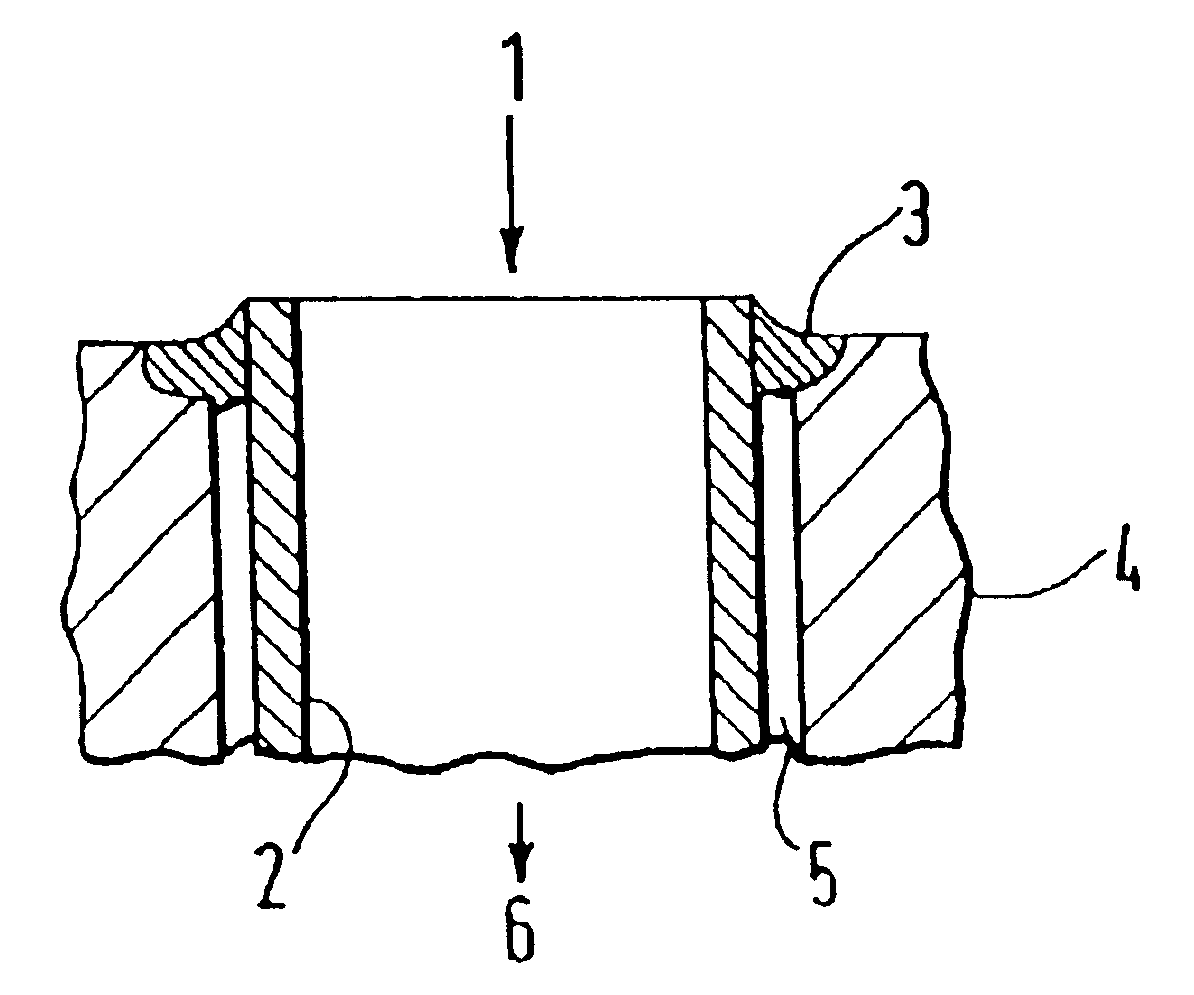
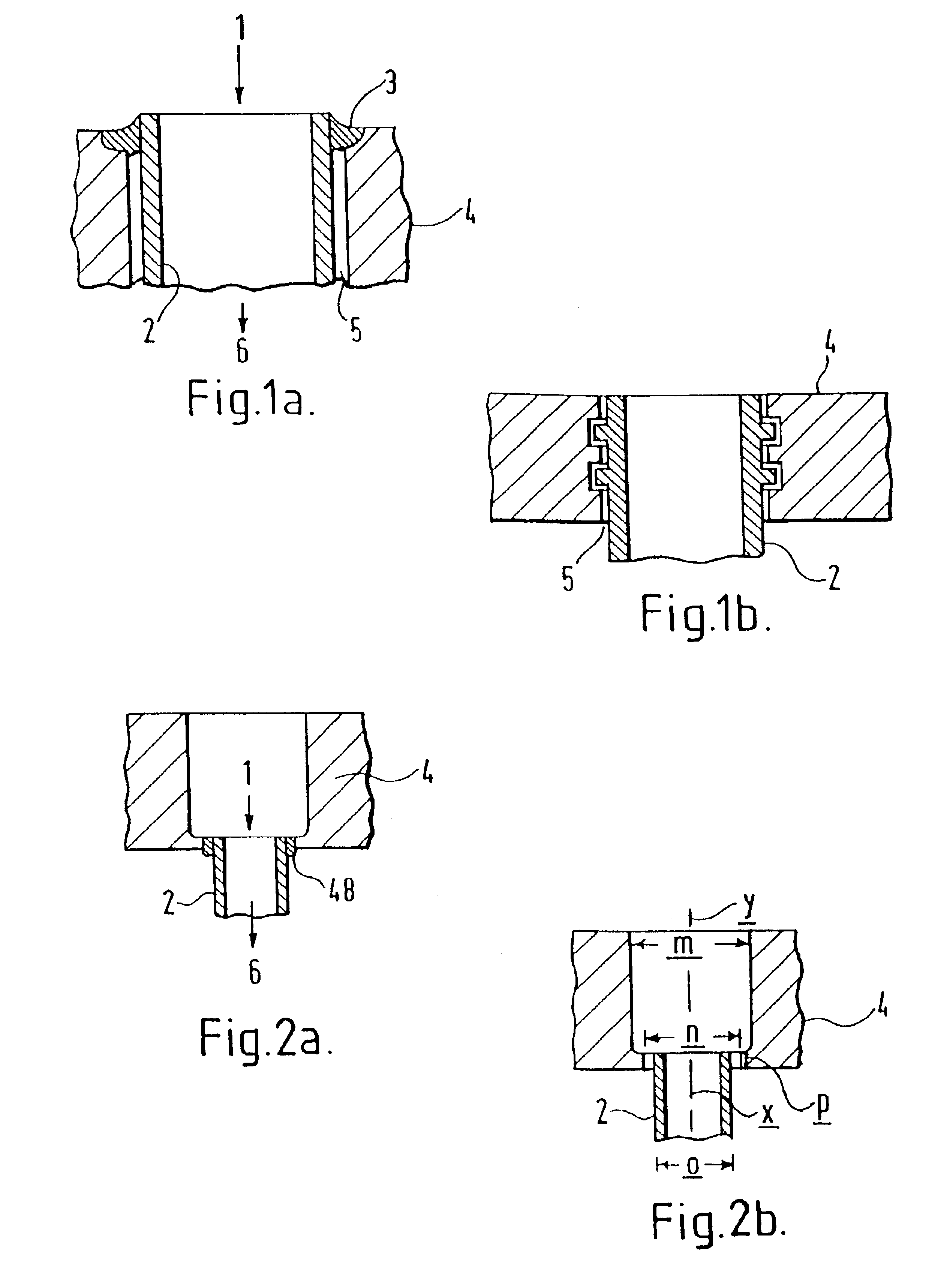
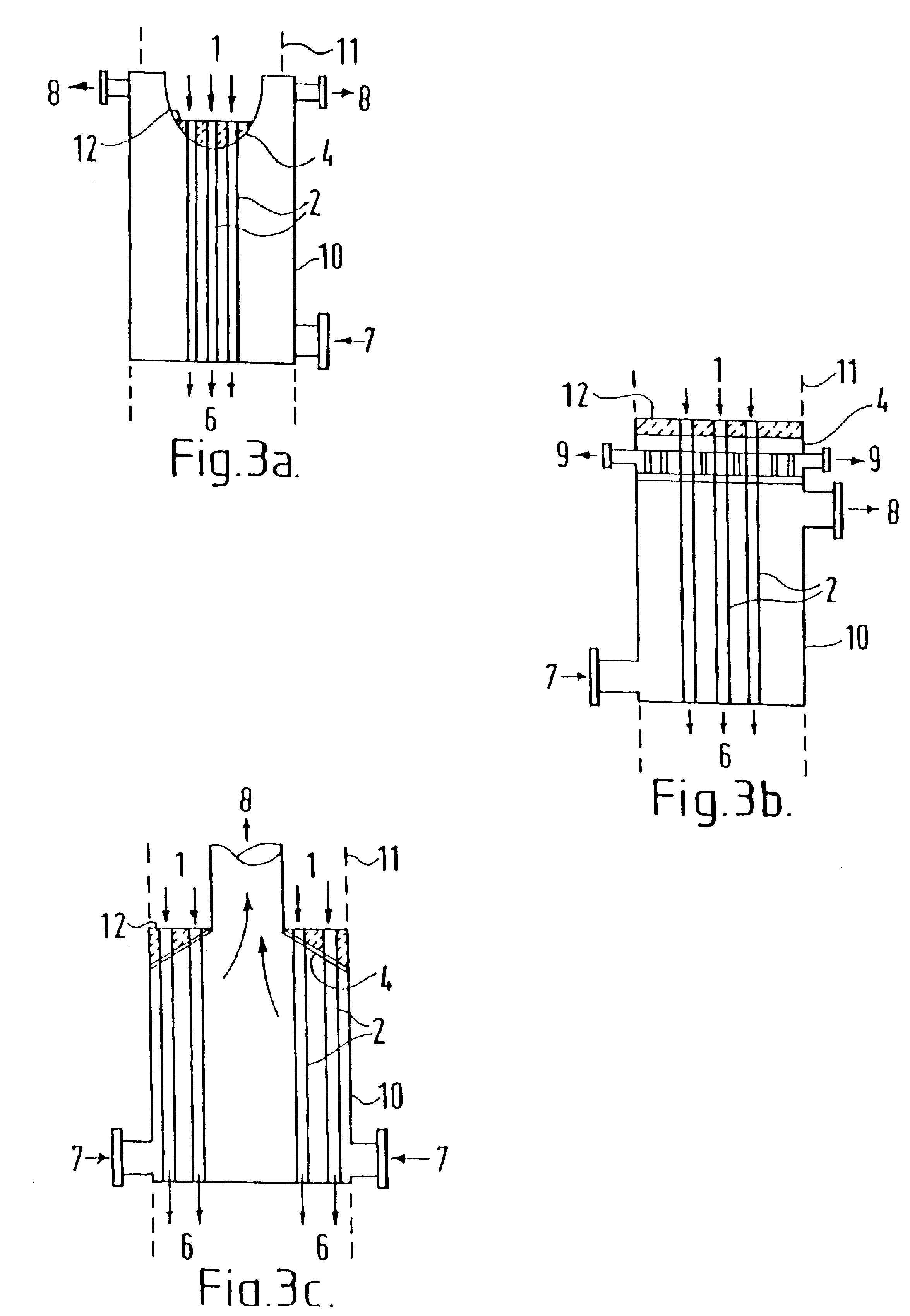
[0095]A hydrogen cyanide reactor was constructed with a shell and tube heat exchanger. The entry tubesheet and heat exchange tubes of the heat exchanger were prepared from a nickel-chromium alloy (INCONEL 600). The entry end of the exchange tubes was flush with the upper surface of the entry tubesheet or the tube ends extended slightly beyond the upper surface of the entry tubesheet. The exchange tubes were welded to the upper surface of the entry tubesheet. A mixture of silicon nitride ferrules and nickel-chromium alloy ferrules (INCONEL 600) were placed in nickel-chromium alloy (INCONEL 600) ferrule sleeves and the ferrules were then inserted in the entry end of the exchange tubes. After approximately 4 months (about 2700 hours) of operation, with 15 operating cycles, that is thermal shocks, and several high temperature (>1200° C.) operating periods, one silicon nitride and one nickel-chromium alloy ferrule were removed and inspected for wear. Each operating cycle consisted of hea...

example 2

[0099]The hydrogen cyanide reactor of Example 1 was operated for an additional 5 months. Again one silicon nitride and one adjacent nickel-chromium alloy ferrule were removed from the reactor and evaluated.

[0100]The nickel-chromium ferrule was difficult to remove from the exchange tube and it showed appreciable length loss, approximately 1 inch (2.54 cm) from the original length. There were also large amounts of carbon / nitrogen deposits on the surface of this ferrule. The ferrule was physically trapped within the sleeve. This ferrule had also swelled from absorbing carbon / nitrogen, thus constricting the inner diameter of the ferrule. Erosion patterns (wall thinning) were also visible on the interior of the ferrule.

[0101]The silicon nitride ferrule was easily removed from the exchange tube and showed no length loss. Some corrosion deposits, likely metal cyanide deposits, were noted on the outside of the ferrule. A dark carbon deposit was noted on the outside exit portion of the ferru...

example 3

[0103]The ferrules from Examples 1 and 2 were analyzed for weight loss and volume change. These results are reported in the Table below. The percentages reported were estimated by comparing the weight and volume of the ferrules from Examples 1 and 2 with that of a corresponding new ferrule.

[0104]

Months ofWeightVolumeFerruleOperationChange (%)Change (%)Silicon Nitride42094-50Nickel-chromium alloy99-109-10

[0105]Thus it can be seen that the silicon nitride ferrules of the present invention are very effective at protecting heat exchange tubes for long periods of time without any significant change in the dimensions of the ferrule.


PUM

PropertyMeasurementUnit
Temperatureaaaaaaaaaa
Angleaaaaaaaaaa
Angleaaaaaaaaaa

Abstract

Disclosed are means for improving the service-life of indirect tubesheet type heat exchangers used in chemical reactors, particularly those exposed to reducing, nitridizing and/or carburizing environments. Such means include the use of certain ferrules within the heat exchange tubes and/or weld types used in construction of these heat exchangers.

Description

CROSS-REFERENCE TO RELATED APPLICATION[0001]This application is a division of prior application Ser. No. 09 / 593,637, filed Jun. 13, 2000, now abandoned entitled “High Performance Heat Exchangers,” which claims the benefit of Provisional application Ser. No. 60 / 141,769, filed Jun. 30, 1999, benefit of which is claimed under 35 U.S.C. §120.BACKGROUND OF THE INVENTION[0002]This invention relates generally to means for improving the service-life and reliability of indirect heat exchangers used in chemical reaction systems which produce high temperature, reactive effluent gasses. In particular, this invention relates to means for improving service-life of indirect heat exchangers used in the production of hydrogen cyanide.[0003]In many chemical processes, the reaction effluent comprises hot, reactive, and / or abrasive fluids and / or gasses. For many of these reactions, it is desirable to rapidly quench the reactor effluent to prevent decomposition of the product component(s). Quenching may...

Claims


Application Information

Patent Timeline
IPC IPC(8): C01C3/02C01C3/00F28F21/08F28F19/00F28F21/00F28F9/08C22C19/05F28D1/04F28F9/16F28F9/18
CPCC01C3/022C01C3/0225C01C3/0233F28F19/002F28F21/082F28F21/087F28D1/04
Inventor BLANDA, JR., PAUL JOSEPHDECOURCY, MICHAEL STANLEY
Owner ROHM & HAAS CO
Why Eureka
Try Eureka