Dielectric filter, antenna duplexer

a technology of dielectric filter and duplexer, which is applied in the direction of electrical equipment, waveguides, resonators, etc., can solve the problems of filter performance decline, filter performance decline, and hardly uniform thickness, and achieve the effect of high q factor of resonators, low loss, and high attenuation

Inactive Publication Date: 2005-11-15
PANASONIC CORP
View PDF17 Cites 52 Cited by
  • Summary
  • Abstract
  • Description
  • Claims
  • Application Information

AI Technical Summary

Benefits of technology

[0008]A dielectric filter includes resonator electrodes made of metallic foil, electro-magnetically coupled with each other, an inter-stage coupling capacitor electrode for coupling the resonator electrodes, an input/output coupling capacitor electrode for inputting and outputting a signal to the resonator electrode...

Problems solved by technology

The resonator electrodes, the inter-stage coupling capacitor electrode, and the input/output coupling capacitor electrodes of the flat, multi-layer dielectric filter are manufactured with printed patterns of conductive paste and thus are hardly have uniform thicknesses.
This reduces a Q-factor of the resonator electrode, and thus the filter has a declining performance.
The conductive paste containing mainly metal powd...

Method used


Image

  • Dielectric filter, antenna duplexer
  • Dielectric filter, antenna duplexer
  • Dielectric filter, antenna duplexer

Examples


embodiment 1

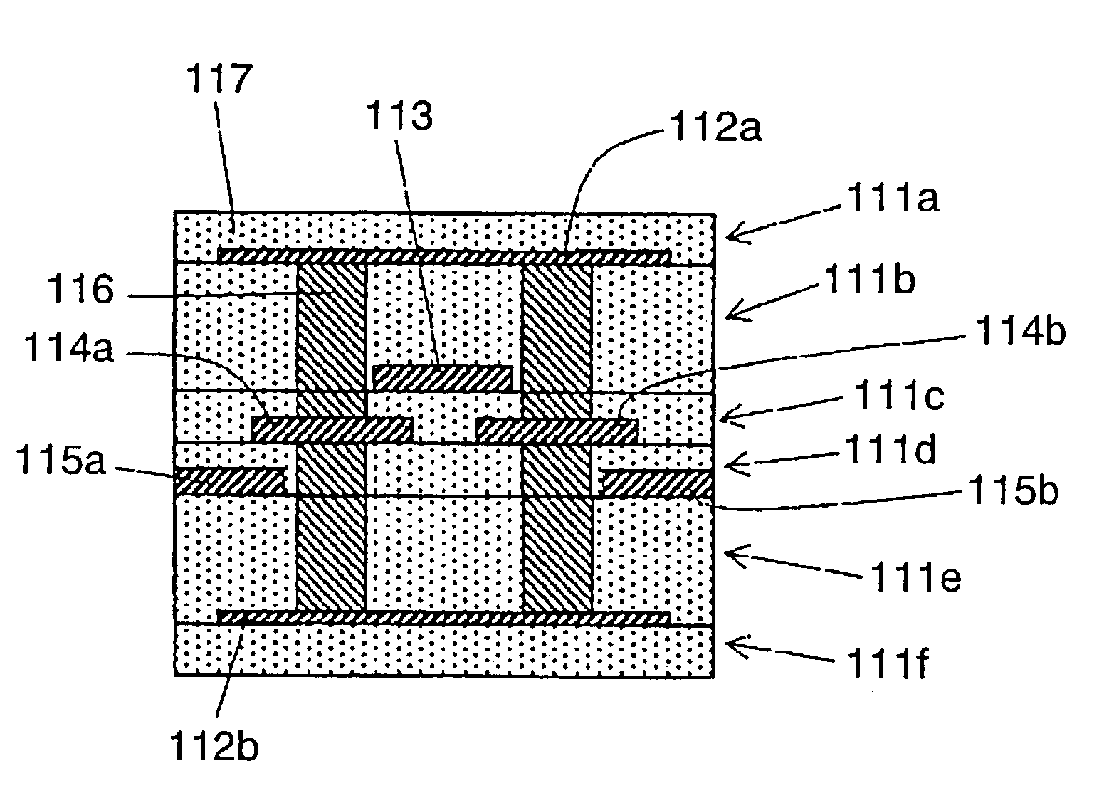
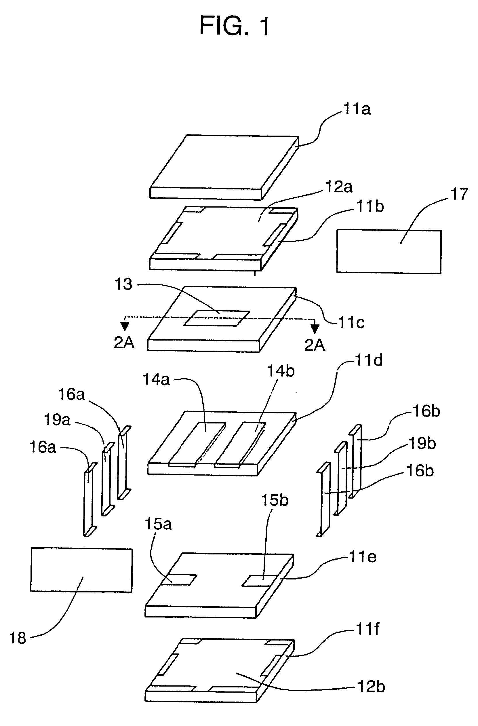
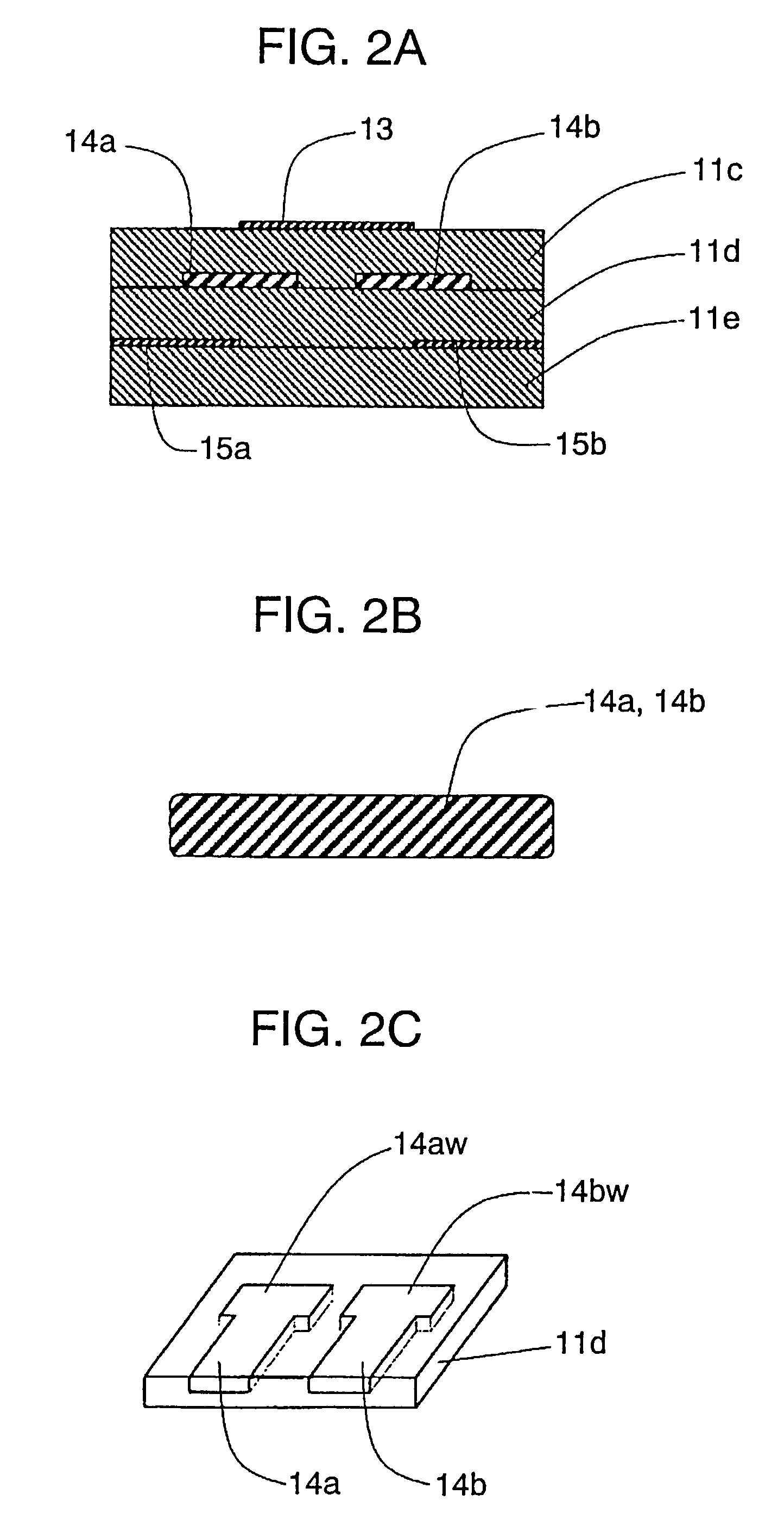
[0029]FIG. 1 is an exploded perspective view of a dielectric filter according to Embodiment 1 of the present invention. The dielectric filter, having a basic arrangement identical to that shown in FIG. 17, includes six dielectric substrates 11a to 11f. The resonator dielectric substrate 11d including resonator electrodes is a ceramic substrate having a high dielectric constant, but may be a resin substrate or a resin composite substrate containing resin material and inorganic filler.

[0030]A shield electrode dielectric substrate 11b includes a shield electrode 12a on the upper surface thereof. An inter-stage coupling capacitor dielectric substrate 11c has an inter-stage coupling capacitor electrode 13 on the upper surface thereof. The resonator dielectric substrate 11d includes resonator electrodes 14a and 14b made of foil containing gold, silver, or copper having a thickness ranging 10 μm to 400 μm on the upper surface thereof. Each resonator electrode has a cross section having a f...

embodiment 2

[0039]FIGS. 3A to 3F illustrate a method of manufacturing a resonator dielectric substrate 27, an essential element of a dielectric filter according to Embodiment 2 of the present invention.

[0040]FIG. 3A is a cross sectional view of the substrate at a line 3A—3A of the plan view of FIG. 3B. Identical patterns of an etching-resist layer 22 are provided by photolithography on both, upper and lower surfaces of a metallic foil 21 containing gold, silver, or copper. The metallic foil 21, when being etched from both sides and then polished at the surface by chemical or electrolytic process, is finished as an electrode frame 24 having resonator electrodes 23 as shown in FIG. 3B. The electrode frame 24 includes positioning guides 25 on inner sides thereof. The electrode frame 24 may be manufactured by die molding.

[0041]FIG. 3C illustrates a cross section of the electrode frame 24. Then, the electrode frame 24 is placed on a dielectric sheet 26 and pressed together from both, upper and lower...

embodiment 3

[0045]Embodiment 3 is differentiated from Embodiment 2 in that a dielectric substrate including a resonator electrode of metallic foil embedded therein is made of composite material containing thermoset resin such as epoxy resin and inorganic filler of powder of Al2O3 or MgO.

[0046]The thermoset resin of the composite material may be made of not only epoxy resin, but also phenol resin and cyanate resin.

[0047]FIGS. 5A to 5F are schematic diagrams essentially illustrating a method according to this embodiment. As shown in FIG. 5A, a protective-ceramic-dielectric substrate 31a as a protective layer in green-sheet form, a shield electrode ceramic dielectric substrate 31b in green-sheet form having a shield electrode 32a, and an inter-stage coupling capacitor ceramic dielectric substrate 31c in green-sheet form having an inter-stage coupling capacitor electrode 33 are laminated and pressed together in directions denoted by arrows. The laminated substrates are then fired at about 900° C. t...


PUM


Abstract

A dielectric filter includes resonator electrodes, an inter-stage coupling capacitor electrode, and an input/output coupling capacitor electrode on dielectric substrates, respectively. The resonator electrodes are electro-magnetically coupled to each other to form a tri-plate structure, are made of a metallic foil embedded in a resonator dielectric substrate. Another dielectric filter includes an upper shield electrode dielectric substrate, an inter-stage coupling capacitor dielectric substrate, a resonator dielectric substrate, and an input/output coupling capacitor dielectric substrate which are made of a composite dielectric material including a high-dielectric-constant material and a low-dielectric-constant material. The above described arrangement provides the dielectric filter with an improved Q factor of a resonator, a low loss, and a high attenuation.

Description

TECHNICAL FIELD[0001]The present invention relates to a dielectric filter for a high-frequency radio apparatus such as a mobile telephone, and particularly to a dielectric filter including strip-line resonator electrodes electro-magnetically coupled with each other provided on a dielectric substrate.BACKGROUND ART[0002]Dielectric filters have recently been used as high-frequency filters in mobile telephones, they particularly are required to have a reduced overall size and thickness. A flat, multi-layer dielectric filter instead of a coaxial filter is now focused. A conventional flat, multi-layer dielectric filter will be explained referring to relevant drawings.[0003]FIG. 17 is an exploded perspective view of the conventional flat, multi-layer dielectric filter. The dielectric filter having a shown layer structure includes six dielectric substrates 1a to 1f. A shield electrode 2a is formed on the upper surface of the dielectric substrate 1b. An inter-stage coupling capacitor electr...

Claims


Application Information

Patent Timeline
IPC IPC(8): H01P11/00H01P1/203H01P1/20H01P1/213
CPCH01P1/20345H01P1/2135H01P11/007
Inventor MAEKAWA, TOMOYASUGAYA, YASUHIROYAMADA, TORUISHIZAKI, TOSHIO
Owner PANASONIC CORP
Why Eureka
Try Eureka