Solid electrolytic capacitor and manufacturing method thereof
a technology of electrolytic capacitors and solid electrolytic capacitors, which is applied in capacitor manufacture, casings/cabinets/drawers, electrical equipment casings/cabinets/drawers, etc., can solve the problems of difficult to reduce esr in a high frequency region, and achieve the effect of preventing flocculation, and further reducing equivalent serial resistance in a high frequency region
- Summary
- Abstract
- Description
- Claims
- Application Information
AI Technical Summary
Benefits of technology
Problems solved by technology
Method used
Image
Examples
##ventive examples 1-7
INVENTIVE EXAMPLES 1-7
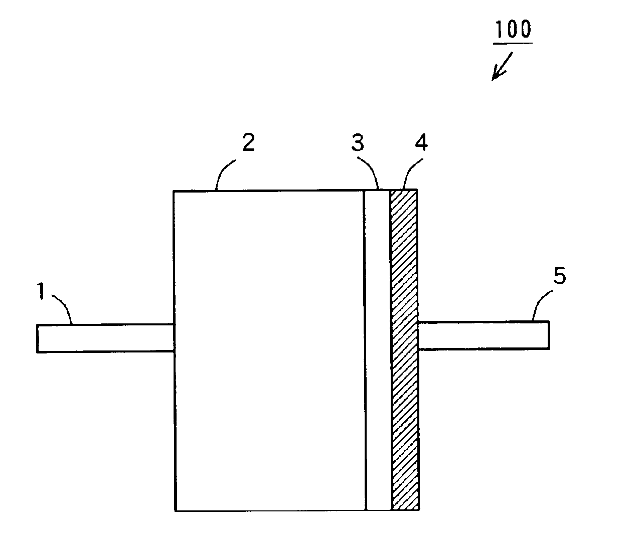
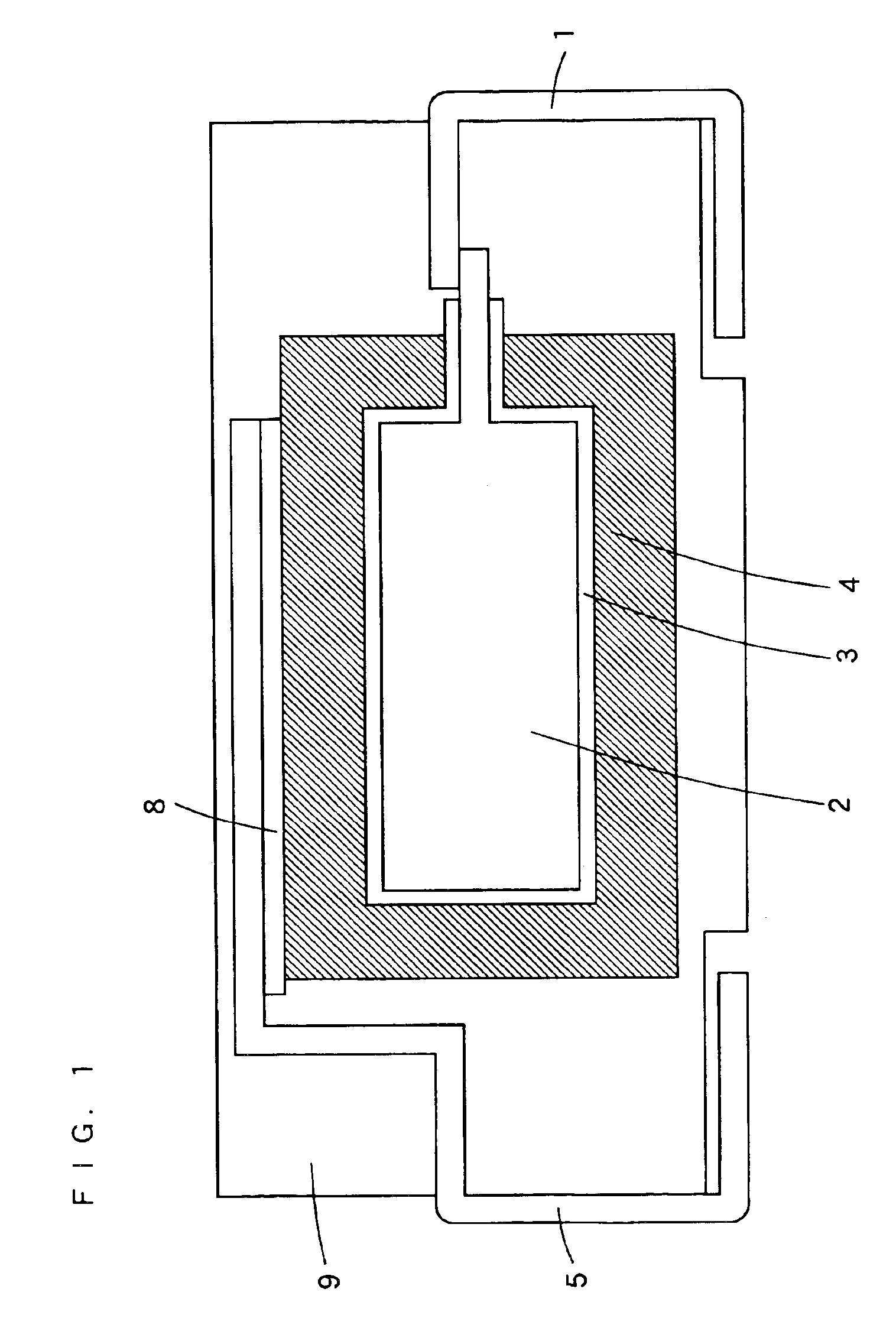
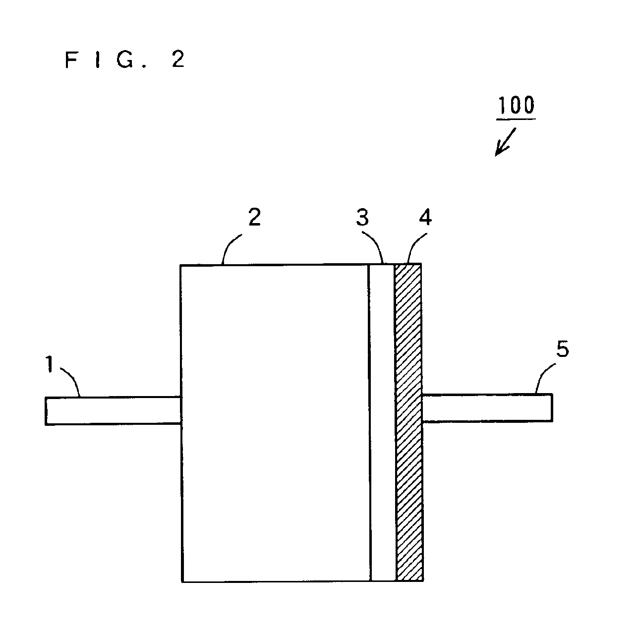
[0066]In the present inventive examples, solid electrolytic capacitors 100 were prepared as shown below in the manufacturing method according to the above-mentioned first embodiment to evaluate the ESRs.
[0067]First, in the inventive examples 1 to 7, the solid electrolytic capacitors 100 were prepared in a following method under following conditions by setting the average particle diameters of the silver particles to 0.009 μm, 0.01 μm, 0.03 μm, 0.05 μm, 0.06 μm, 0.07 μm, and 0.09 μm, respectively.
[0068]Using polyethyleneimine as a protective colloid, 70% by weight of silver particles and 30% by weight of polyethyleneimine were mixed. Then, 60% by weight of the mixed substance and 40% by weight of an organic solvent of ethanol were mixed to prepare a silver paste.
[0069]Subsequently, an anode 2 composed of a porous sinter was formed by sintering the powder of tantalum particles, and the formed anode 2 was oxidized in an aqueous solution of phosphoric acid to form ...
##ventive example 8
INVENTIVE EXAMPLE 8
[0071]In the present inventive example, a solid electrolytic capacitor 100 was prepared in the manufacturing method according to the above-mentioned second embodiment to evaluate the ESR.
[0072]An anode 2 composed of a porous sinter was formed by sintering the powder of tantalum particles, and the formed anode 2 was oxidized in an aqueous solution of phosphoric acid to form a dielectric layer 3 composed of a dielectric oxide film on the surface of the anode 2.
[0073]Subsequently, the anode 2 bearing the dielectric layer 3 was immersed in an ammoniacal silver nitrate solution, and then added with 3% by weight of glucose to form a metal layer 4 on the dielectric layer 3 by electroless plating. Note that the ammoniacal silver nitrate solution is produced by adding 0.15 mol / l of ammonia water into 3 mol / l of silver nitrate solution.
[0074]The anode 2 was then connected with an anode terminal 1, and the metal layer 4 was connected with a cathode terminal 5.
##ventive examples 9-13
INVENTIVE EXAMPLES 9-13
[0091]In inventive examples 9 to 13, solid electrolytic capacitors 100 were prepared in the same manner under the same conditions except that the drying temperatures for the silver pastes were set to 140° C., 145° C., 150° C., 160° C., and 170° C., respectively. The inventive example 11 was the same as the above-mentioned inventive example 3.
[0092](Evaluation)
[0093]The solid electrolytic capacitors 100 of the inventive examples 9 to 13 were each measured for the ESRs at a frequency of 100 kHz using an LCR meter.
[0094]Table 2 shows the ESR measurement results of the solid electrolytic capacitors 100 of the inventive examples 9 to 13. Note that the respective ESR measurement results of the solid electrolytic capacitors 100 of the inventive examples 9 to 13 are normalized by the ESR measurement result of the solid electrolytic capacitor of the inventive example 9 as 100, and the normalized ESR values are represented in Table 2.
[0095]
TABLE 2Drying Temperature(° C....
PUM
| Property | Measurement | Unit |
|---|---|---|
| particle diameter | aaaaa | aaaaa |
| particle diameter | aaaaa | aaaaa |
| temperature | aaaaa | aaaaa |
Abstract
Description
Claims
Application Information
 - R&D
- Intellectual Property
- Life Sciences
- Materials
- Tech Scout
- Unparalleled Data Quality
- Higher Quality Content
- 60% Fewer Hallucinations
Browse by: Latest US Patents, China's latest patents, Technical Efficacy Thesaurus, Application Domain, Technology Topic, Popular Technical Reports.
© 2025 PatSnap. All rights reserved.Legal|Privacy policy|Modern Slavery Act Transparency Statement|Sitemap|About US| Contact US: help@patsnap.com


