Rational frequency synthesizers

Inactive Publication Date: 2005-12-20
WI LAN INC
View PDF1 Cites 19 Cited by
  • Summary
  • Abstract
  • Description
  • Claims
  • Application Information

AI Technical Summary

Benefits of technology

[0038]It is therefore an objective of the present invention to provide a single loop PLL frequency synthesizer which uses very high reference clock frequency (in the order of 100 MHz, consistent with the current state of the art of the integrated circuits technology, but inherently not limited to this operating frequency) and operates at very high comparison frequencies (of the same order as the reference clock frequency) thus substantially reducing the total division ratio Ntot, and therefore proportionally reducing the noise multiplication factor in the loop, resulting in improved phase noise of synthesized signals.
[0040]It is yet another objective of the present invention to utilize high speed digital XOR gates, operated in a single sideband (SSB) mode as the means for phase comparison, thus further reducing the noise levels in the loop and freeing the loop of the “dead zone” effects.
[0042]It is another objective of the invention to, by internal waveforms synthesis, mathematical algorithms, computation, analysis and by other means in the design process determine and choose the optimum fractional expansions representing the ratio of oscillator and reference frequency, for each and every synthesized frequency, and so obtain the bases for the hardware implementation and design, where the computation in the design stage includes the spectral purity analysis of each and every frequency, using such means as computation of time domain waveforms and division of, Fast Fourier Transform (FFT), inverse FFT and other means, with the goal to choose the optimum or minimum hardware configuration of the synthesizer, one which meets the criteria of best spectral purity in the frequency range of interest (usually in the vicinity of the LB W), such as to minimize the spectral energy occurring at frequencies equal to step frequency fstep and it's harmonics, so that the loop bandwidth of the synthesizer's PLL can be maximized, possibly to values greater than the frequency of the step size increment.
[0046]It is yet another objective of the present invention to provide a PLL frequency synthesizer capable of supplying an oscillator signal with precisely controlled phase and ability to control (increment / decrement) the phase in fine steps.

Problems solved by technology

As is well known in the art, excessive phase noise of the sources used to process modulated signals that contain information in it's phase or frequency can cause degradation in signal to noise ratio (S / N) or bit error rate (BER) of the desired signal, resulting in reduced sensitivity and unsatisfactory system performance.
In the systems with closely spaced channels, it is also possible that the LO phase noise can cause degradation in sensitivity due to adjacent channel interference, whereby the LO phase noise side bands can in the receiver down-convert the adjacent channel and place it directly on the desired signal and so cause interference, or in the case of a transmitter LO, the transmitted LO phase noise side band occurring at the adjacent channel frequency can cause direct interference in the receivers tuned to that adjacent channel frequency.
As is well known in the art, the discrete spurious sidebands of the synthesized signal are none less important than the random phase noise sidebands, since they can cause similar, and in many cases even worse undesired effects.
Each of the above techniques has its advantages and disadvantages regarding frequency coverage, frequency agility and switching speed, phase noise and spurious sideband performance, power consumption, size, cost, manufacturability, repeatability etc.
DAS—possibly the best spectral purity (phase noise, close-in spurs) and fastest switching time attainable, wide frequency coverage but limited frequency agility, larger size, higher complexity and cost, may require adjustments in manufacturing—in general not suitable for large volume, low cost applications.
DDS—very good noise and close-in spectral purity performance, fast switching with continuous phase capability, excellent agility but limited frequency coverage (currently at about 100 MHz practical implementation limit), medium to high cost (increases with frequency), could be used in limited number of high volume applications.
This noise is added to the phase noise of the reference signal.
As will be shown later, this noise multiplication is often the key factor causing degradation of phase noise performance in synthesizers.
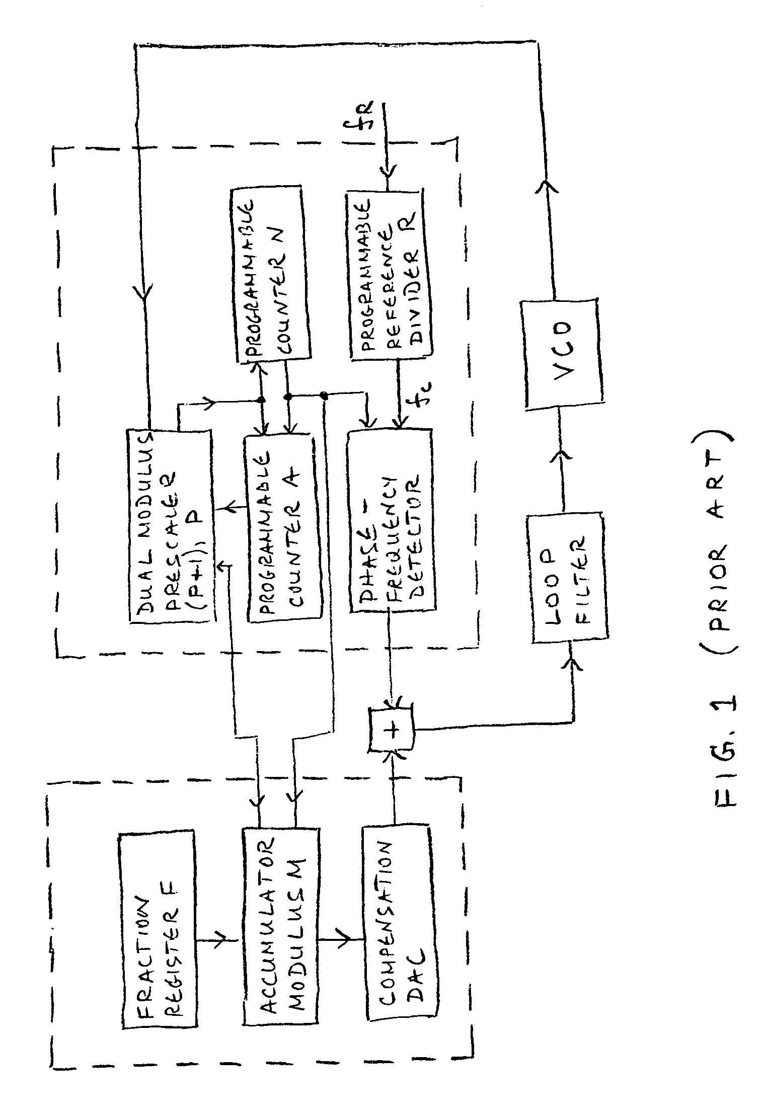
Since programmable counters have limitations in terms of the upper frequency limit where they can operate, often prescalers are used to scale the oscillator frequency down and bring it within the operational frequency range of the programmable counters.
As is well documented in the literature related to the art, the primary cause of phase noise at the output of the synthesized oscillators s the combination of the residual VCO phase noise (the portion of the oscillator noise that is not rejected by the loop), and the noise power of the loop components (such as dividers and phase detectors).
In the case of relatively low comparison frequency fc and relatively high oscillator frequency fosc, the 20·log(Ntot) figure can amount to a very large quantity, exceeding the residual VCO phase noise and thus becoming a dominant and limiting factor in the ultimate noise performance achievable in the system.
The noise gain of this magnitude can place severe limitations as to the achievable phase noise performance in the system, such as in the above two examples.
Another adverse effect of low comparison frequency indirectly affects the switching speed.
While in this way the switching speed is improved, the oscillator noise rejection remains poor with narrow LBW.
Another adverse effect associated with narrow LBW is related to phase modulation of the oscillator due to mechanical shock or vibration (referred to as microphonics).
In general, mechanical vibration can cause parametric modulation of various components of a PLL (such as varactor diodes, inductors, etc.), which can result in phase modulation of the oscillator.
The loop will reject the spectral energy of the mechanical vibration within the LBW, but outside the LBW, the loop will not be able to protect the oscillator of being phase modulated by the vibration.
Clearly, the limitation of this type of the synthesizer only aggravates the issues discussed above, and in many applications it can not provide the satisfactory performance.
This error signal needs to be completely removed from the loop, otherwise severe phase modulation of the oscillator would occur (it can be shown that the accumulated phase error in one complete fractional cycle amounts to 360° at the oscillator frequency).
Although it is achievable in the state of the art FNS ICs, it is often difficult to maintain this kind of precision over wide frequency range and temperature range since both the compensation DAC and PFD will exhibit some variations due to these factors.
For wide tuning range oscillators, it is often necessary to provide an external adjustment for the compensation current of the DACs in the application circuit (outside of the IC), which may complicate the manufacturing process.
Due to these factors, the ultimate phase error compensation is limited, and to ensure sufficient spectral purity of the oscillator, the loop filter often must be called upon to assist in further reduction of the sidebands, resulting in the LBW having a cut-off much below the fc / M, i.e. much below the step increment frequency.
The reduced LBW, as mention earlier may adversely affect both the switching speed and the rejection of the internal oscillator phase noise.
Finally, it should be mentioned that all of the above discussed prior art synthesizers use a phase-frequency detector which is inherently limited in speed.
The propagation delay and set-up and hold times of this circuit limits the maximum speed (or frequency) of the PFD operation.
This is a point where phase detector gain goes to zero, which can cause instability in the loop, resulting in random phase fluctuation (low frequency phase noise) of the oscillator.

Method used


Image

  • Rational frequency synthesizers
  • Rational frequency synthesizers
  • Rational frequency synthesizers

Examples


Embodiment Construction

[0068]The heart of the present invention is the Frequency Ratio Generator (FRG). The basic principle of operation of the FRG relies on the fact that output frequency (oscillator fosc) and input frequency (reference clock fref) always have a rational relationship, i.e. the ratio of the two can always be represented as a ratio of two integer numbers, P and Q, as shown in equation (6):

fosc / fref=P / Q or fosc=fref*P / Q  (6)

[0069]Alternatively, fosc / fref ratio can be expressed as a combination of two fractions, per eq. (6a):

fosc*P1 / Q1=fref*P2 / Q2  (6a)

which is equivalent to factoring P / Q into:

P / Q=(P2*Q1) / (P1*Q2)  (6b)

[0070]If the ratio P / Q can be realized in hardware, such that a frequency equal to fref*P / Q is generated, then all what it would take to realize eq. (6) would be to use a PLL and phase lock the oscillator to this frequency. The manner in which the FRG accomplishes this goal is described below.

[0071]It is well known in the science of mathematics that any rational number P / Q can b...


PUM


Abstract

A single loop PLL frequency synthesizer for operation in the MHz to GHz range, suitable for integration in integrated circuits, operates at high comparison frequencies thus achieving superior phase noise performance, having wide loop bandwidths while able to tune in small frequency steps. It is based on the fact that the output frequency and the reference clock frequency always have a rational relationship, and so can always be represented as a ratio of two integer numbers. This ratio is expanded into various expressions of equivalent fraction expansions taking the form of a series of divided, added or subtracted terms, each being a rational number in itself. This ratio is realized in hardware through stages of frequency conversions using single sideband mixers (either the upper or lower sideband, and frequency dividers. This process of frequency translation thus generates the comparison frequency to which the PLL phase-locks the VCO.

Description

BACKGROUND OF THE INVENTION[0001]1. Field of the Invention[0002]This invention relates to a new class of phase lock loop (PLL) frequency synthesizers utilizing very high reference clock frequency (in the order of 100 MHz, but not limited to) and very high comparison frequencies (of the same order as the reference clock frequency), but providing fine frequency resolution, where frequency steps increments can be orders of magnitude smaller (in the order of 10 kHz, but not limited to) than the comparison frequency, and especially to their use as single loop PLL frequency synthesizers having very low phase noise, thus offering significant performance improvements for advantageous applications such as cable television (CATV), high speed digital communications (digital TV and high speed cable data modems for internet applications), wireless communications and other consumer and commercial electronics devices in high frequency (HF), very high frequency (VHF) and ultra high frequency (UHF) ...

Claims


Application Information

Patent Timeline
IPC IPC(8): H03B21/02H03L7/08H03B21/04H03L7/16
CPCH03B21/025H03B21/04H03L7/16
Inventor PETROVIC, BRANISLAVASHKENASI, MAX
Owner WI LAN INC
Why Eureka
Try Eureka