[0013]A further
advantage of the present invention is derived from the use of jet disturbers in one or several of the primary sets of elements. The use of a jet disturber in connection with an ion funnel was first described in U.S.
patent application Ser. No. 09 / 860,721, filed May 18, 2001, and entitled “
Ionization Source Utilizing A Jet Disturber In Combination With An
Ion Funnel And Method Of Operation,” the entire contents of which are hereby incorporated herein by this reference. As described in U.S.
patent application Ser. No. 09 / 860,721, a “jet disturber” is simply a
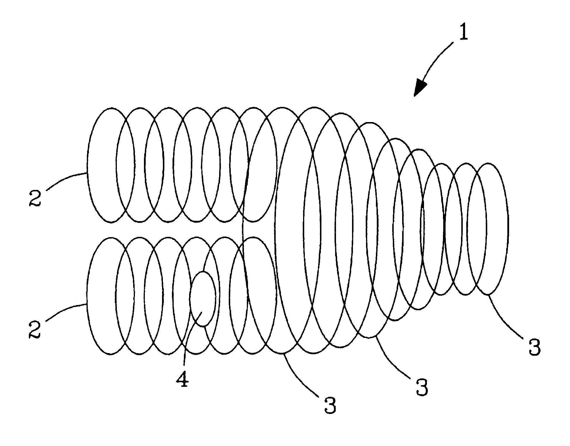
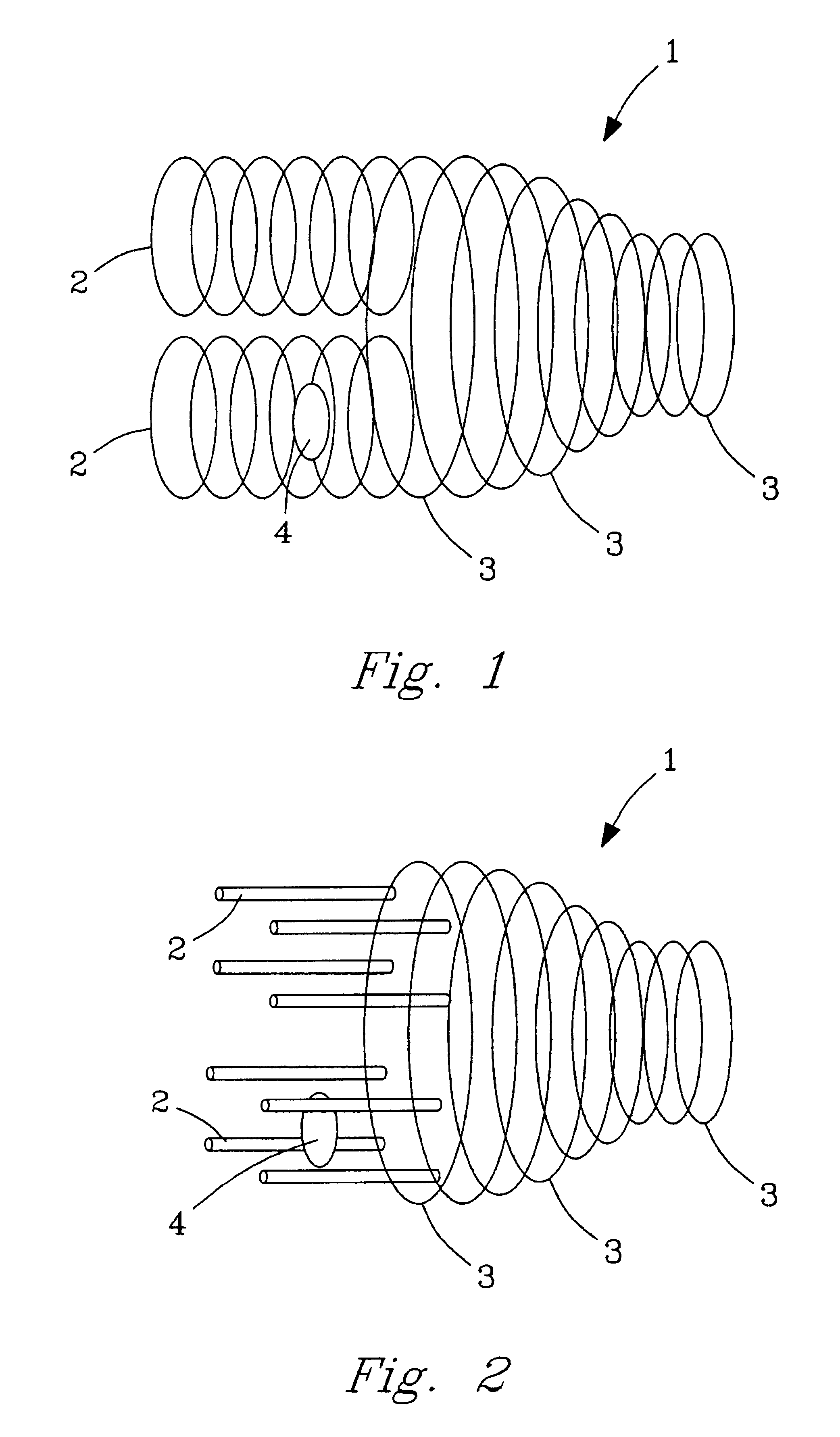
physical barrier placed inside the apertures of an ion funnel. Referring again to FIG. 1, a jet disturber 4 is shown within the primary elements 2. Typically, a jet disturber is provided as a
metal disk. As described in U.S.
patent application Ser. No. 09 / 860,721, the placement of a jet disturber in this manner will greatly enhance ion conductance.
[0014]As with the description of the ion funnel contained in U.S. Pat. No. 6,107,628, It is important to note that the while the present invention utilizes the concept of the jet disturber taught in U.S. patent application Ser. No. 09 / 860,721, it also expands and greatly extends the utility of those concepts, and does so in a manner that relieves the invention of many of the limitations of U.S. patent application Ser. No. 09 / 860,721. Thus, while the description herein relies on the disclosure of U.S. patent application Ser. No. 09 / 860,721 to teach the rudimentary concepts of an jet disturber, the present invention should in no way be viewed as limited by the disclosure of U.S. patent application Ser. No. 09 / 860,721. For example, while U.S. patent application Ser. No. 09 / 860,721 describes the jet disturber as preferably being used in conjunction with a multi-
capillary inlet, for purposes of this disclosure, such is not necessarily required.
[0015]One aspect by which the present invention expands and extends the utility of the jet disturber is through the use of voltages applied to the jet disturber. In contrast to the enhanced ion conductance generally associated with the use of a jet disturber as taught in U.S. patent application Ser. No. 09 / 860,721, the use of an applied
voltage can have the opposite effect. For example, a suitable
dc voltage applied to the jet disturber can attract ions passing through the primary set of elements, thereby preventing them from passing. Alternatively, another suitable
dc voltage applied to the jet disturber can repel ions passing through the primary set of elements, also preventing them from passing. In between these two extremes, the passage of ions can thus be easily controlled by the application of
voltage to the jet disturber. As will be recognized by those having skill in the art, the voltage applied to the jet disturber can be easily controlled with a suitable power supply, and may further be rapidly changed as desired by the user. Thus, the present invention is further enhanced by the use of jet disturbers connected to a power supply in one or more of the primary sets of elements, as this allows the user to readily adjust the passage of ions through that primary set of elements.
[0016]The present invention is thus a multi-source ion funnel for introducing ions from a region at relatively high pressures to a region at relatively low pressures having at least two sets of primary elements having apertures, each set of elements having a receiving end and an emitting end, the first sets of elements configured to receive a ions from at least two separate ion sources at the receiving ends, and a secondary set of elements having elements having a receiving end and an emitting end, the secondary set of elements configured to receive said ions from the emitting end of said primary sets of elements. The multi-source ion funnel may further utilize at least one jet disturber positioned within the interior of at least one of said sets of primary elements, and may include a means for providing a voltage to the jet disturber.
[0017]As utilized in a mass
spectrometer, the present invention includes at least two electrospray ion sources, at least two capillary inlets, and a mutli-source ion funnel, wherein each of the electrospray ion sources is configured to direct ions generated by the electrospray sources into and through each of the capillary inlets, and the capillary inlets are further configured to direct the ions into the receiving end of the sets of primary elements.
[0018]The present invention is thus also a method for introducing ions generated in a region of relatively
high pressure into a region of relatively low pressure by providing at least two electrospray ion sources, providing at least two capillary inlets configured to direct ions generated by the electrospray sources into and through each of the capillary inlets, providing at least two sets of primary elements having apertures, each set of elements having a receiving end and an emitting end, the primary sets of elements configured to receive a ions from the capillary inlets at the receiving ends, and providing a secondary set of elements having apertures having a receiving end and an emitting end, the secondary set of elements configured to receive said ions from the emitting end of the primary sets of elements and emit said ions from said emitting end of the secondary set of elements. The method may further include the step of providing at least one jet disturber positioned within at least one of the sets of primary elements, providing a voltage, such as a dc voltage, in the jet disturber, thereby adjusting the transmission of ions through at least one of the sets of primary elements. The step of adjusting the transmission of ions may prevent the transmission of ions, and the applied voltage may be applied intermittently, for example as a
square wave form, thereby providing intermittent disruption of the ions.

