Magnetic recording apparatus and magnetic recording method

a recording apparatus and magnetic technology, applied in the field of magnetic recording apparatus and magnetic recording method, can solve the problems of physical limit of recording density, difficulty in continuing to meet the demand of high speed and high recording density in the future, and exchange-coupling interaction may not work between the magnetic particles, etc., to achieve high sensitivity and great merit on the part of the industry

Active Publication Date: 2006-01-03
KK TOSHIBA
View PDF5 Cites 47 Cited by
  • Summary
  • Abstract
  • Description
  • Claims
  • Application Information

AI Technical Summary

Benefits of technology

[0018]According to the embodiment of the invention, the high-density recording exceeding a thermal-agitation limit becomes realizable by writing in magnetization of a record layer by the current whose spin is pola...

Problems solved by technology

However, it is said that there is a physical limit in a recording density.
By using the conventional method, it is thought to be difficult to continue meeting the demand of high speed and high recording density in the future.
Therefore, the magnetic particles need to be magnetically divided each other by a non-magnetic body so that an exchange-coupling interaction may not work between the magnetic particles.
Therefore, it becomes impossible for a magnetic reversal unit to hold the magnetic domains.
Therefore, by using the magnetic field which the conventional recording head may generate, recording will become impossible, if Ku is enlarged.
However, if Va is enlarged by increasing the size of the magnetic particle in a medium, high-den...

Method used


Image

  • Magnetic recording apparatus and magnetic recording method
  • Magnetic recording apparatus and magnetic recording method
  • Magnetic recording apparatus and magnetic recording method

Examples


first example

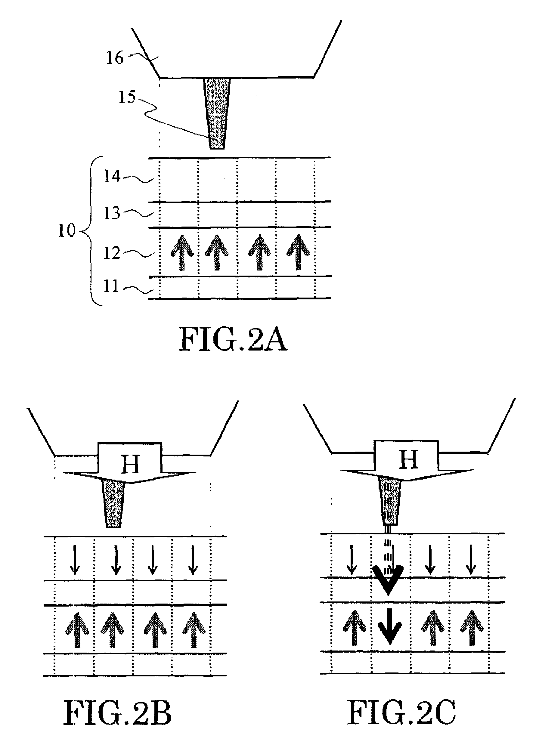
[0103]FIG. 11 is a conceptual diagram showing the sectional structure used in this example.

[0104]That is, in the high-polarized spin control layer 14 of a recording medium, the chromium oxide (CrO2) which has rutile type structure was used. Moreover, cobalt platinum (CoPt) was used in the recording layer 12. Copper (Cu) was used in the intermediate layer 13. Gold (Au) was used in the electrode layer 11.

[0105]First, the gold (Au) electrode layer 11 was formed in the back side of the silicon (Si) substrate S. Next, the cobalt platinum (CoPt) layer 12 was formed on silicon substrate S, and copper (Cu) was grown on it. Furthermore, chromic oxide (CrO2) was formed on it. The thickness of cobalt platinum (CoPt) was made about 20 nm, the thickness of copper (Cu) was made about 5 nm and the thickness of chromic oxide (CrO2) was made about 10 nm.

[0106]Next, the probe 15 was formed by coating the surface of a silicon (Si) short needle with gold (Au) The probe 15 had a cone-like shape and the ...

second example

[0114]FIG. 13 is a schematic diagram showing the sectional structure used in this example.

[0115]That is, first, the gold (Au) electrode layer 11 was formed on the back side of the silicon (Si) substrate S so that it became ohmic contact. And 5 nm (FePt) of iron platinum was formed as a recording layer 12 on the silicon substrate S, 5 nm (Cu) of copper was laminated as an intermediate layer 13 on it, and 20 nm (ZnO:Co) of zinc oxides which included cobalt was laminated on it as a high-polarized spin control layer 14. Furthermore, the gold (Au) electrode 19 was formed on it by using a mask (not shown) in order to pass a current to a direction perpendicular to the film plane.

[0116]By VSM measurement, it was confirmed that the iron platinum (FePt) single film had Hc of about 9 kOe(s), and that the magnetization easy axis thereof was perpendicular to the film plane. Moreover, it was confirmed that the cobalt added zinc oxide (ZnO:Co) has soft magnetic characteristics.

[0117]When the magne...

third example

[0122]FIG. 14 is a schematic diagram showing the sectional structure used in this example.

[0123]That is, the platinum (Pt) base layer 20 with a thickness of about 50 mn, the iron platinum (FePt) recording layer 12 with a thickness of about 5 nm, the copper (Cu) intermediate layer 13 with a thickness of about 5 nm, and the lanthanum oxide strontium manganese (La0 7Sr0 3MnO3) high-polarized spin control layer 14 with a thickness of about 20 nm were laminated by the sputtering method in this order on the aluminum substrate 11. At the time of sputtering film formation, the substrate 11 was heated at 300 degrees C.

[0124]It was confirmed in advance that the La0 7Sr0 3MnO3 high-polarized spin control layer 14 showed a half metallic characteristic.

[0125]Next, the cylindrical clusters with a diameter of about 50 nm were formed by lithography, etching, and lift-off technique. The space between the clusters was filled with the insulator 18. Then, the laminating of the carbon (C) protection lay...


PUM


Abstract

A magnetic recording apparatus comprises a magnetic field impression unit, a current supplying unit and a controlling unit t. The magnetic field impression unit impresses a magnetic field to a magnetic recording medium. The current supplying unit supplies a current to the magnetic recording medium. The controlling unit makes the current supplying unit supply the current to the magnetic recording medium while making the magnetic field impression unit impress the magnetic field to at least a unit of a magnetic recording unit of the magnetic recording medium. Thus, a information is recorded magnetically by making a direction of a magnetization of the magnetic recording unit of the magnetic recording medium in a predetermined direction.

Description

CROSS-REFERENCE TO RELATED APPLICATIONS[0001]This application is based upon and claims the benefit of priority from the prior Japanese Patent Application No. 2002-097446, filed on Mar. 29, 2002; the entire contents of which are incorporated herein by reference.BACKGROUND OF THE INVENTION[0002]This invention relates to a magnetic recording apparatus and a magnetic recording method, and more particularly, to a magnetic recording apparatus and a recording method which realize a super-high-density magnetic recording that exceed the thermal-agitation limit of a recording medium.[0003]With improvement in the processing speed of a computer in recent years, magnetic memory storage, such as HDD (Hard Disk Drive) which performs recording and reproduction function of information or data, is needed to have a higher recording density and a higher operating speed. However, it is said that there is a physical limit in a recording density.[0004]By using the conventional method, it is thought to be ...

Claims


Application Information

Patent Timeline
IPC IPC(8): G11B5/02G11B5/64G11B5/00G11B5/65G11B5/66G11B5/738G11B9/00G11B9/04G11B11/08G11B11/10G11B13/00
CPCB82Y10/00G11B5/00G11B11/08G11B11/10G11B9/04G11B2005/0005G11B2005/0002G11B9/1409
Inventor KAI, TADASHITAKAGISHI, MASAYUKISAHASHI, MASASHIAKIYAMA, JUNICHIIWASAKI, HITOSHIKIKITSU, AKIRA
Owner KK TOSHIBA
Why Eureka
Try Eureka