Processless digitally imaged photopolymer elements using microspheres

a technology of photopolymer elements and microspheres, which is applied in the direction of photosensitive materials, instruments, photomechanical equipment, etc., can solve the problems of limited print performance, uncured non-image areas, water-developable printing plates, waste of resources, etc., and achieve the effect of reducing the final density of the photopolymer formulation

Inactive Publication Date: 2006-01-24
MACDERMID PRINTING SOLUTIONS
View PDF41 Cites 65 Cited by
  • Summary
  • Abstract
  • Description
  • Claims
  • Application Information

AI Technical Summary

Benefits of technology

[0024]Another aspect of the invention is to provide a method of making a laser imageable printing element using a collapsible cross-linkable material that comprises...

Problems solved by technology

In addition, water-developable printing plates have inherent disadvantages, such as limited print performance and the generation of wastewater.
Since the photopolymer is “dense”, removing of the uncured non-image areas takes a substantial amount of time to achieve.
Once again, because of the high density of these materials, the thermal engraving step is long and tedious.
Additionally, high resolution is difficult to achieve.
Thus, the disadvantage of prior art engraved plates is a combination of limited resolution and throughput.
However, CO2 engraving lasers lack beam resolution and cause anomalies due to heat dissipation.
The resolution of such systems is limited to well below 133 lines per inch (LPI) on a practical basis.
However, these lasers lack the necessary power and reactivity to engrave conventional photopolymers and may be too slow due to mass transfer limitations in dense “cured” photopolymer or rubber systems.
CITR photopolymer sleeve products with limited performance have been available to the market for many years.
A problem with the prior methods of joining the edges to form a continuous cylinder is that sometimes the...

Method used


Image

  • Processless digitally imaged photopolymer elements using microspheres
  • Processless digitally imaged photopolymer elements using microspheres
  • Processless digitally imaged photopolymer elements using microspheres

Examples


example 1

Preparation of a Processless Flexographic Plate Using Unexpanded Microspheres Sensitive to 830 nm Lasers

[0121]A printing plate is manufactured according to the composition listed in Table 4, using unexpanded microspheres (Expancel DU microspheres). The ingredients are mixed in a Sigma mixer, and the temperature of the mixer is slowly and gradually increased, until it reaches the “optimum” expansion temperature for the unexpanded microspheres to increase their volume. The optimum expansion temperature is determined through routine experimentation, and depends on the particular type and size of unexpanded microspheres that are used. Care is taken not to exceed the “maximum” expansion temperature so as to avoid microsphere collapse. The composition is hot-pressed between 2 clear polyethylene terephthalate sheets (PETs) at a temperature that is below the maximum expansion temperature of the microspheres. One of the two PETs has a slip film or release coating to facilitate easy removal.

[...

example 2

Preparation of a Processless Flexographic Plate Using Unexpanded Microspheres Sensitive to 1064 nm Lasers

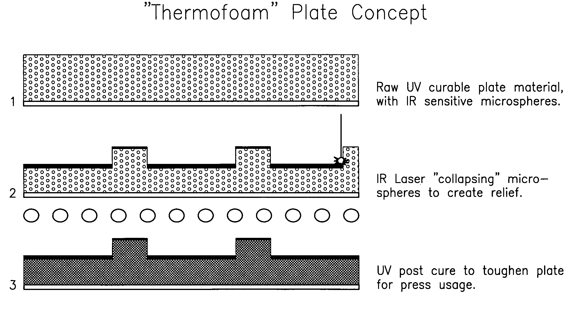
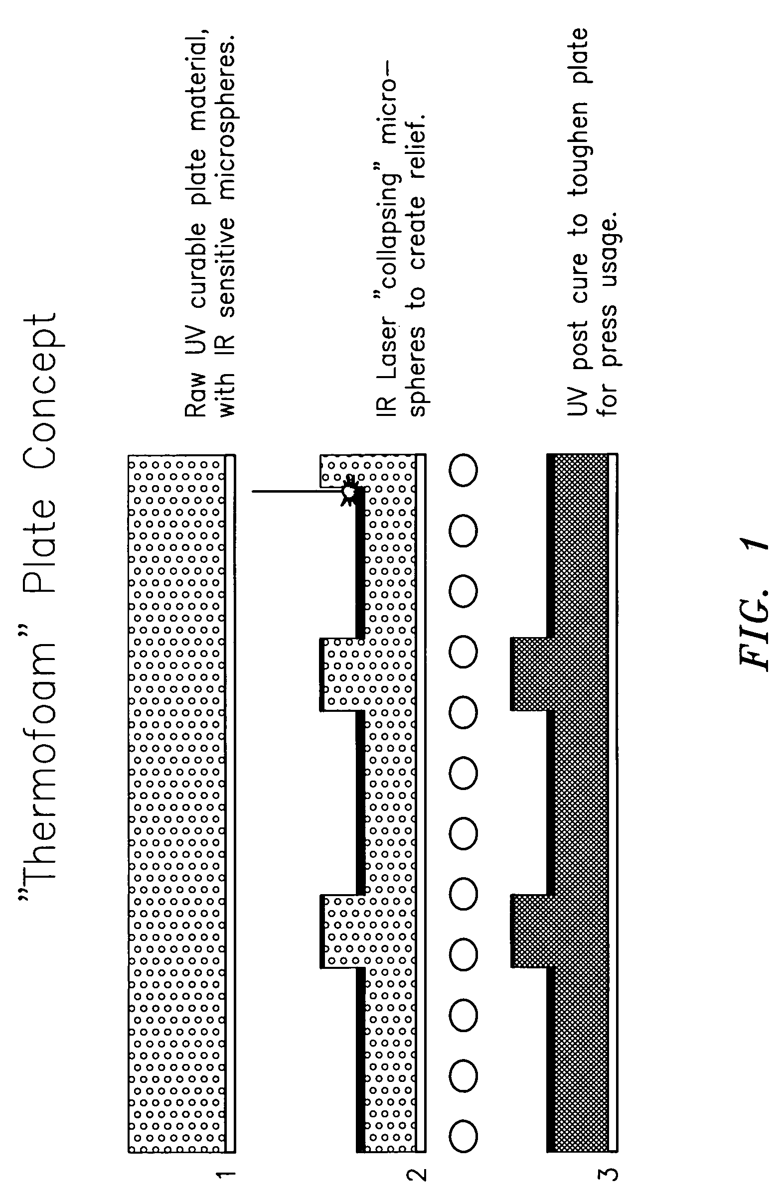
[0126]A similar procedure to Example 1 is followed, using the composition listed in Table 5, where the microspheres are unexpanded microspheres (Expancel DU microspheres). The subsequent plate development and manufacture is the same as in Example 1, except that a commercially available 1064 nm plate-setter such as Barco's CDI™ is used instead. The digital file from the computer is transferred onto the plate. In the areas where the laser interacts with the photopolymer, the microspheres collapse, creating a relief. Different energy densities are employed to create areas of deep and shallow relief.

[0127]During the main laser collapse step, a “flash” or “bump” exposure is used throughout to collapse a monolayer on the surface to form a denser layer and create the ultimate printing surface. The plate is cured by a conventional face exposure and post-cured to hold 1% dots at 133 lines...

example 3

Preparation of a Processless Flexographic Plate Using Expanded Microspheres Sensitive to 830 nm Lasers

[0129]A printing plate is manufactured according to the composition listed in Table 4, using expanded microspheres (Expancel DE microspheres). The ingredients are mixed in a Sigma mixer, and the compound is hot-pressed between 2 clear PETs, one of which has a slip film or release coating. Alternately, the plate is manufactured in a twin-screw extruder.

[0130]After lamination, the coversheet is removed and discarded. The plate is back-exposed through the backing, and mounted on a commercially available 830 nm flexographic plate-setter such as Creo's ThermoFlex® 5280. The digital file from the computer is transferred onto the plate. In the areas where the laser interacts with the photopolymer, the microspheres will collapse, creating a relief. Different energy densities are employed to create areas of deep and shallow relief.

[0131]During the main laser collapse step, a “flash” or “bump...


PUM


Abstract

Laser imageable flexographic printing elements, including printing plates and printing sleeves and methods of making the laser imageable flexographic printing elements using a collapsible cross-linkable material comprising a curable elastomer, a material that absorbs laser radiation at a selected wavelength, and microspheres are disclosed. A laser is used to collapse and melt the collapsible cross-linkable material to form a relief image on the printing element. The printing element is thereafter cured by face exposure to crosslink and cure the formed relief image. The invention addresses a market need for eliminating chemical processing of printing elements, thus going from printing element to press much more quickly and using an environmentally friendly process.

Description

CROSS REFERENCE TO RELATED APPLICATIONS[0001]This application is a continuation-in-part of application Ser. No. 10 / 105,898, filed on Mar. 25, 2002, now U.S. Pat. No. 6,806,018, the subject matter of which is herein incorporated by reference.FIELD OF THE INVENTION[0002]The present invention relates to photosensitive elastomeric compositions used to prepare digitally imaged photopolymer printing elements, such as printing plates and printing sleeves, without the need for any interim process steps.BACKGROUND OF THE INVENTION[0003]Flexography is a method of printing that is commonly used for high-volume runs. Flexography is employed for printing on a variety of substrates such as paper, paperboard stock, corrugated board, films, foils and laminates. Newspapers and grocery bags are prominent examples. Coarse surfaces and stretch films can be economically printed only be means of flexography. Flexographic printing plates are relief plates with image elements raised above open areas. Such ...

Claims


Application Information

Patent Timeline
IPC IPC(8): G03F7/032G03F7/11G03F7/039G03F7/26G03F7/38B41C1/05B41C1/18B41N1/12G03F7/027
CPCB41C1/05B41C1/182B41N1/12Y10S430/165G03F7/027
Inventor KANGA, RUSTOM SAM
Owner MACDERMID PRINTING SOLUTIONS
Why Eureka
Try Eureka