
Imaging apparatus for exposing a printing member and printing members therefor

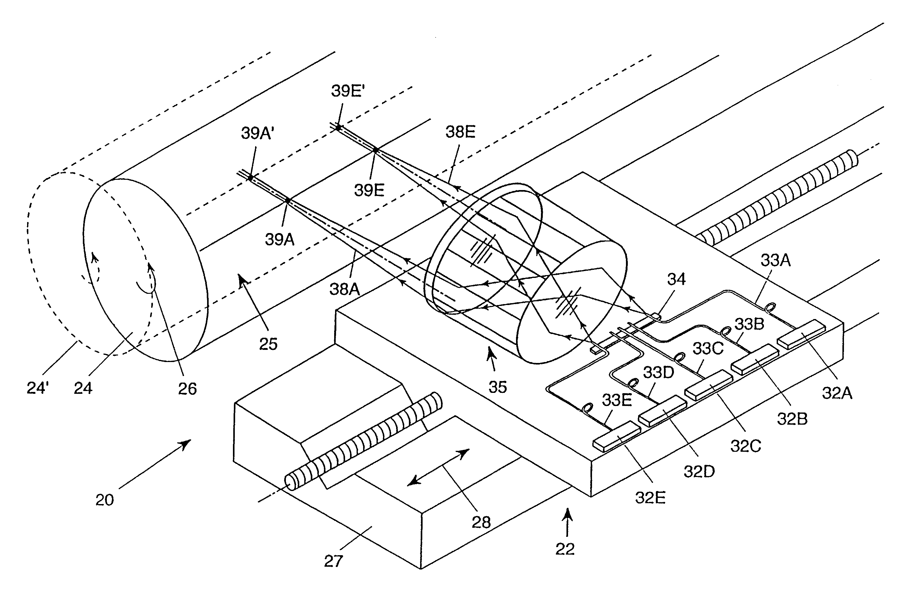
a printing member and imaging apparatus technology, applied in the field of lithographic offset printing, can solve the problems of prone to mechanical failure, and increasing the cost and complexity of imaging apparatus, so as to reduce the distance between the surface coating layer and the inked image, save time and labor costs, and achieve the effect of reducing the cost of imaging apparatus

Inactive Publication Date: 2006-01-24
A I T ISRAEL - ADVANCED IMAGING TECH
View PDF36 Cites 7 Cited by
  • Summary
  • Abstract
  • Description
  • Claims
  • Application Information

AI Technical Summary

Benefits of technology

[0025]There is also provided, in accordance with a preferred embodiment of the present invention, a method for controlling the spot size of an imaging apparatus which includes a plurality of IR laser diodes each coupled to a corresponding optical fiber, the optical fibers are aligned at a distance from an exposure surface and providing an output light beam, and a stationary telecentric lens assembly which operates to image the output light beam onto the exposure surface. The method includes the step of selectively varying during exposure the intensity of the laser diodes so as to reduce or increase the spot size resulting thereby.
[0035]The present invention also includes printing members. These printing members of the present invention overcome the above mentioned drawbacks in the existing plates and / or printing members, as the printing members of the present invention have improved printability, improved sensitivity and improved ease of cleaning. Additionally these printing members can be imaged both on and off press.
[0037]The radiation absorbing layer is of a material oleophilic to ink and absorbs ablative energy, preferably from a low-energy infra-red laser, such that at least a partial thickness of the radiation absorbing material remains, post ablation, to support an image to be transferred to a printing medium, such as paper, and for attracting and retaining ink dispersed onto the printing member, from an ink roller or the like. Since this intermediate layer carries the image and retains the ink, the distance between the surface coating layer and the inked image is minimized. This minimal distance provides the printing member with desired characteristics, similar to those of planographic plates, as the printing member can be inked quicker and easier, saving time and labor costs. Since the ink is closer to the surface of the printing member, printing with the printing member requires less pressure from the drums, cylinders, rollers, other components and the like (of the press or the like), resulting in less wear and longer usable life for this printing member. Moreover, this printing member may be cleaned automatically or manually on-press.

Problems solved by technology

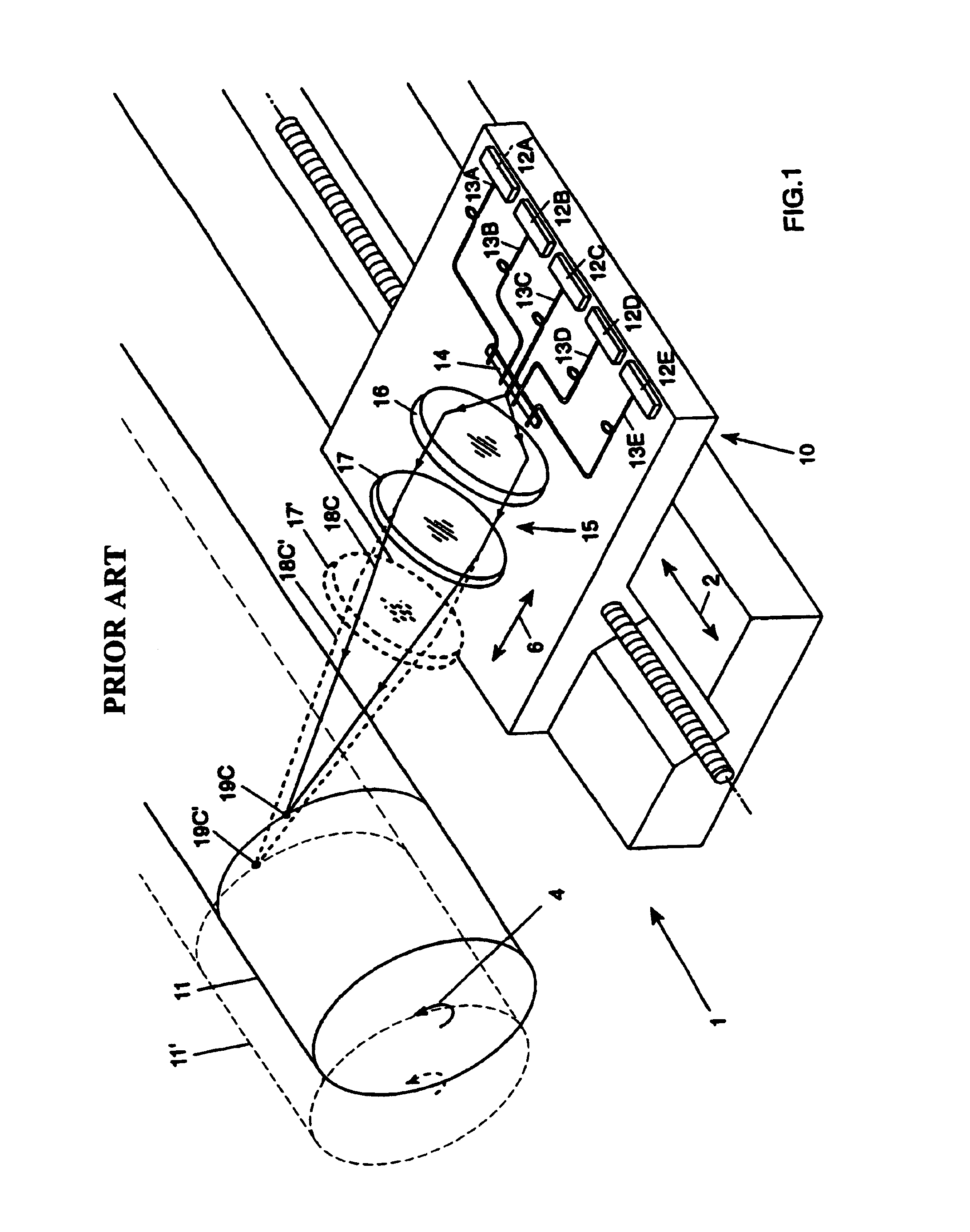
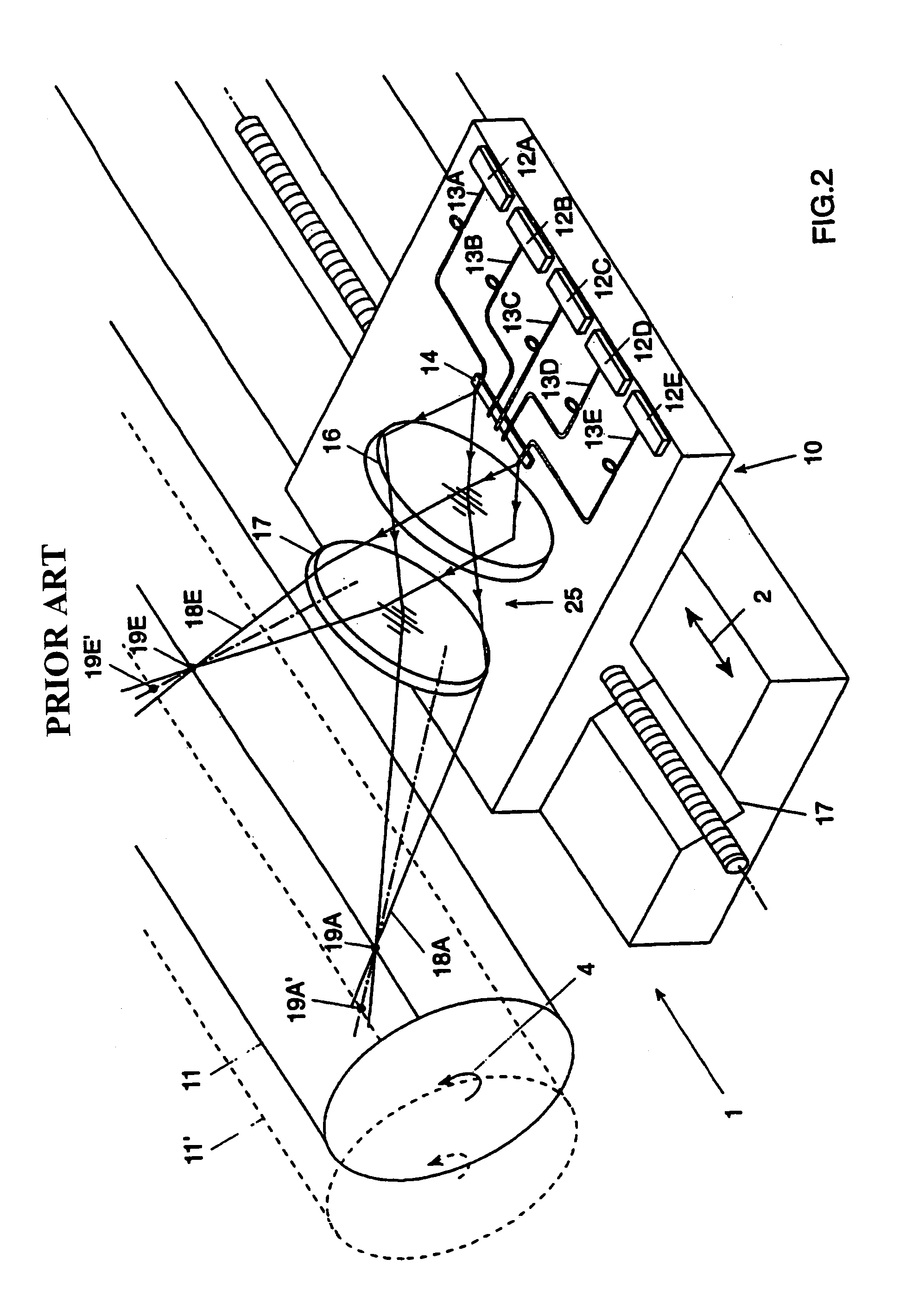
Thus, a large number of lenses are required, whereby the complexity and the cost of the imaging apparatus increase.
One drawback of IR laser diodes is that in order to obtain the output power required to expose the IR sensitive medium, fiber optics with a large diameter, typically 100 microns, and a large numerical aperture, typically larger than 0.2, are required.
A drawback autofocusing optical assemblies, in particular ones which provide an accuracy of the exposed spot in terms of location and spot size on the order of microns is their cost and complexity and the fact that they are prone to mechanical failures.
Initially, the complete removal of the ablated top oleophobic coating and the infra-red radiation absorbing intermediate layers, which together may be several microns thick, results in a physical difference in height above the substrate layer.
This in turn reduces the plate run life, because the increased pressure creates additional wear on the plate, shortening its usable life.
This increased pressure also increases the chances of physical damage to the plate during running, such that a printing run may have to be prematurely terminated due to a damaged plate.
In addition, because the surface of the image deeply depressed from the polysiloxane surface layer of the plate, the portions of the substrate to be imaged are set back from the inking roller (ink transferring source) at a distance such that there is a reduction in the ease of initial inking up of the plate.
This increases the inking or coloring time for the plate and blanket cylinders, and subsequently, the number of copies necessary to be run before fully inked up copies start appearing.
Another drawback with these plates, that effects their imaging quality, is associated with their cleaning.
However, where the ablation energy is relatively low, it is necessary to clean these plates thoroughly.
However, automatic cleaning subjects unimaged areas to unnecessary cleaning, that can damage the background (remaining plate layers), and thus, reduce plate life.
Cleaning also has to reach the depressed areas of the substrate, thus increasing cleaning difficulties.
A further difficulty with the plates is their lack of sensitivity to the infra-red radiation.
This poor sensitivity results in using multiple high energy lasers in an array, that adds to printing costs.

Method used


Image

  • Imaging apparatus for exposing a printing member and printing members therefor
  • Imaging apparatus for exposing a printing member and printing members therefor
  • Imaging apparatus for exposing a printing member and printing members therefor

Examples


example 1

[0092]The following coating formulation was prepared as a mixture (all numbers designating parts in the formulation are in parts by weight of the entire formulation);

[0093]

Neorez 9679 (aqueous dispersion of polyurethane - Zeneca50partsCorp.)Direct Black 19 INA dye solution (Zeneca Corp.)100partsTriton X-100 (Iso-Octylphenoxypolyethanol sold by BDH0.9partsPoole, Dorset, England)Tint-Ayd NV7317 (aqueous black dispersion - Daniel88partsProducts Company)2-Butoxy ethanol8partsNeocryl ® CX-100 cross linking agent (Zeneca Corp.)8partsAntara 430 (vinylpyrrolidone / styrene copolymer - GAF,50partsCorp., Wayne, New Jersey)Water (distilled)50parts

[0094]This mixture was coated onto 175 micron thick Melinex 339 base polyester sheet to a weight of 4 grams per square meter and dried for three minutes at 140° C. The coating was left for one week, during which it became increasingly resistant to rubbing with or without solvent (isopropanol).

[0095]The coating was then treated with a proprietary silicon...

example 2

[0099]A solvent based two component polyurethane was used as a pre-coating on a 175 micron thick Melinex 339 polyester sheet. The polyurethane components, Adcote 102A (Morton Adhesives Europe) and Catalyst F (Morton Adhesives Europe), were mixed in the ratio of 100 parts to 6.5 parts by weight. The mixture was then diluted with 80 parts by weight of methyl ethyl ketone, and the resultant mixture was coated on the Melinex 339 sheet with a wire wound rod, forming the pre coating. This pre-coating was dried in an oven for two minutes at 120° C. to a dry coating weight of one gram per square meter. The pre-coating was kept for a day before coating the next layer.

[0100]The following formulation was then prepared as a mixture (all numbers designating parts in the formulation are in parts by weight of the entire formulation);

[0101]

Desotech EO48102partsFlammruss 101 Carbon50.4partsToluene186partsDibutyl Phthalate5parts

[0102]The mixture was subject to ball-mill mixing for 6 hours and then 1 ...

example 3

[0103]The following mixture for a first coating was made up (all numbers designating parts in the mixture are in parts by weight of the entire mixture):

[0104]

Tynt-Ayd 1379 (Daniel Products Company)97.5partsToluene105partsNeocryl CX-100 Cross linker1.3parts

[0105]The mixture was coated on 175 micron thick Melinex 506 sheet and dried to a coating weight of 5 grams per square centimeter.

[0106]The following silicone mixture (all numbers designating parts in the mixture are in parts by weight of the entire mixture) was then prepared:

[0107]

SS4331 (GE Silicones-General Electric Company,330partsWaterford, New York) 0SS8010 (GE Silicones)4.7partsSS 4300C (GE Silicones)3.3partsToluene670parts

[0108]The mixture was coated onto the first coating to a weight of 1 gram per square meter and dried at 150° C. for 5 minutes.


PUM


Abstract

Apparatus, including a printing system, press, press components, and printing members for lithographic printing and other similar processes, is disclosed. The printing system for imaging printing members includes a plurality of infra red laser diodes coupled to a respective optical fiber for providing an output light beam, and a stationary telecentric lens assembly, that operates to image a printing member by exposure from ablative infra-red radiation. The printing members include a first substrate layer, with a second radiation absorbing layer over this first layer, for supporting an image ablated onto the printing member. A third surface coating layer is over the second layer. The third layer is substantially abdhesive to ink while the second layer has an affinity for ink opposite that of the third layer. Methods for imaging with the apparatus and for imaging the printing members are also disclosed.

Description

[0001]This is a continuation of international application Serial No. PCT / IL97 / 00028, filed 22 Jan. 1997, which is incorporated herein by reference.FIELD OF THE INVENTION[0002]The present invention relates to lithographic offset printing and components employed in apparatuses therefor. In particular, the present invention is directed to an imaging apparatus for a printing system which comprises a plurality of infra red (IR) laser diodes and a telecentric lens assembly, a cylinder assembly and a printing member.BACKGROUND OF THE INVENTION[0003]Arrays comprising a plurality of laser diodes are well known in the art. In one application of laser diode arrays, individual diodes can be modulated so as to expose an IR sensitive printing member on a drum. In one known application, the drum is part of a thermal printer as described for example in U.S. Pat. Nos. 5,109,460 and 5,168,288 assigned to Eastman Kodak Company (Kodak) of Rochester, N.Y., U.S. In a second application, the drum may be a...

Claims


Application Information

Patent Timeline
Patent Type & Authority Patents(United States)
IPC IPC(8): B41J2/45B41J2/46G02B27/64B41C1/10B41J2/475B41N1/00
CPCB41C1/1033B41N1/003B41J2/4753
Inventor FIGOV, MURRAYSTEINBLATT, SERGEBEN OREN, ILANBENEZRA, ALBERT
Owner A I T ISRAEL - ADVANCED IMAGING TECH
Learn More