Method for fabricating, modifying or repairing of single crystal or directionally solidified articles

a technology of directionally solidified and sx, which is applied in the direction of machine/engine, manufacturing tools, and solventing apparatus, etc., can solve the problems of limiting the applicability of this otherwise useful process, complex process, and only feasible reconditioning of such components

Active Publication Date: 2006-02-14
ANSALDO ENERGIA IP UK LTD
View PDF28 Cites 32 Cited by
  • Summary
  • Abstract
  • Description
  • Claims
  • Application Information

AI Technical Summary

Benefits of technology

[0010]It is the aim of the present invention is to provide an advanced method for the repair, modification and small batch manufacture of single crystal components such as those used in gas turbine engines.
[0012]According to the present invention, it is proposed that single crystal isothermal brazing be employed for replacing significant or deep portions of a blade undergoing repair or modification or for creating a standard blank blade from machined sections in the case of rapid prototyping. Isothermal brazing is a proven process for the joining of parts while maintaining their single crystal character. Because the composition of the brazed joint is near or identical to the substrate composition, a melting process such as epitaxial or non-epitaxial laser metal-forming can be successfully used on top of a brazed joint with no ill effects. In that way a coating layer can be applied. Quality of the joints, in terms of its single crystal character, is also better than attempted single crystal welded junctions.
[0015]With the online monitoring system and using automatic feedback control of at least one process parameter such as laser power it is possible to establish and maintain optimum process conditions during the laser metal-forming process. In this favourable case the columnar to equiaxed transition (CET) and melt pool convection are avoided and a temperature field is created in the melt pool which leads to defect-free, epitaxial growth of the deposited material. Thus, it is possible to add new material without creation of grain boundaries. Beside the laser power process parameters like the relative speed between laser beam and the substrate, the carrier gas flow and mass feed rate of added material can be controlled.

Problems solved by technology

However, the process is complicated when single-crystal components have to be refurbished.
Reconditioning of such components is only feasible if the single crystal microstructure can be maintained during the repair process.
However, there are serious limitations, which limit the applicability of this otherwise useful process.
Firstly, control over the deposited material, though thoroughly adequate for predominantly surface-based operations, is difficult to maintain as deposits become large and extensive.
A second barrier to the metal forming of large monoliths is simply that the mass deposition rates, currently available in the art of epitaxial laser metal forming, would make the formulation of such artefacts an extremely time consuming operation.
Thirdly, the powder stream may not be directed in all places it would be desired, because the proximity of the edges of other parts of the component obstruct the gas / power stream and make the process enviable.
This limits the usefullness of the process in certain repair and modification operations.
This limits the usefulness of the process in certain repair and modification operations.
But, even if particles featuring a single crystal structure are used, the structure of the repaired crack as a whole due to the braze alloy differs with respect to material properties from the single-crystal structure of the base material which leads to weakness problems of the brazed joint.
The same problem occurs with the repair methods disclosed in U.S. Pat. Nos, 4,381,944 or 5,437,737 where a braze alloy and a filler material are used at the same time to increase the strength of the brazed joint.

Method used


Image

  • Method for fabricating, modifying or repairing of single crystal or directionally solidified articles
  • Method for fabricating, modifying or repairing of single crystal or directionally solidified articles
  • Method for fabricating, modifying or repairing of single crystal or directionally solidified articles

Examples


Embodiment Construction

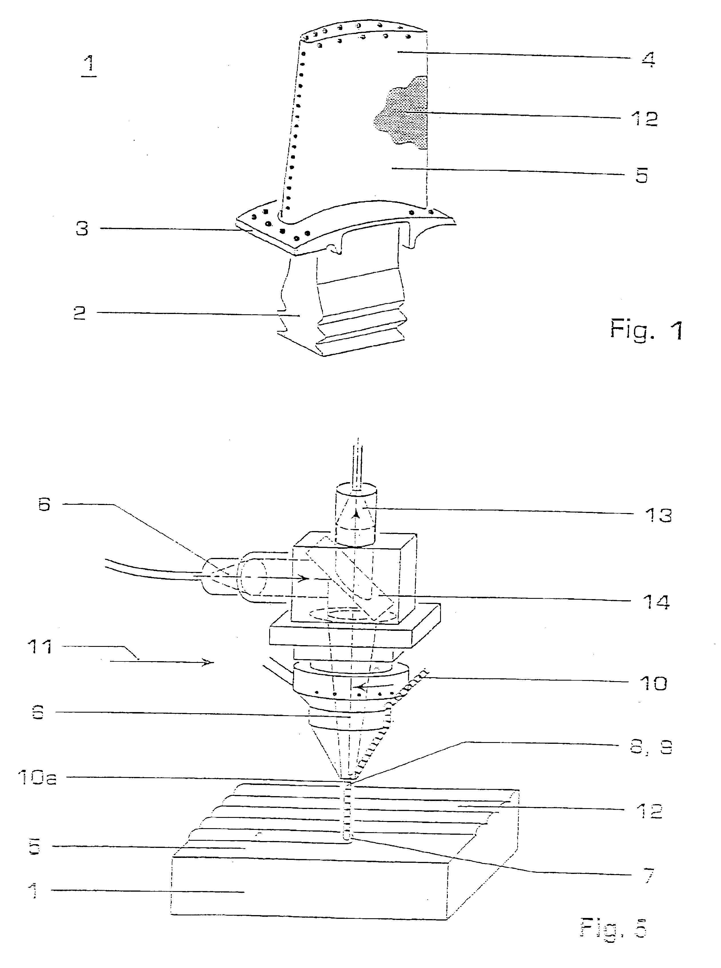
[0023]FIG. 1 shows a single crystal (SX) or directionally solidified (OS) article 1 such as blades or vanes of gas turbine engines, the gas turbine blade comprising a root portion 2, a platform 3 and a blade 4 and having a surface 5. The article 1 can as an example be made from a nickel or cobalt based super alloy. Investment casting methods for producing such SX or DS articles are known e.g. from the prior art U.S. Pat. Nos. 4,960,501, 3,690,367 or EP-A1-0 749 790. These articles 1 are normally made from a nickel or cobalt base super alloy.

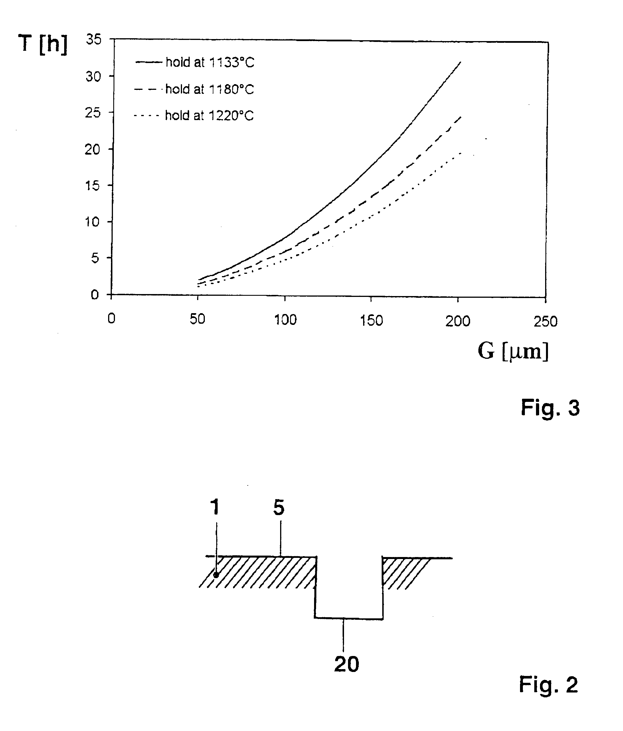
[0024]The herein disclosed method can be used for fabricating, modifying or repairing of such single crystal (SX) or directionally solidified (DS) articles 1. Thereby in a first step of the inventive method two single crystal (SX) or directionally solidified (DS) prefabricated parts are joint together by using an iso-thermal brazing operation with a brazing material. According to FIG. 2 where a gap 20 or crack of the surface 5 of gas turbine arti...


PUM

PropertyMeasurementUnit
temperaturesaaaaaaaaaa
temperatureaaaaaaaaaa
massaaaaaaaaaa

Abstract

It is disclosed a method for fabricating, modifying or repairing of single crystal or directionally solidified articles. Two single crystal or directionally solidified prefabricated parts are joint by isothermally brazing using a brazing material. After that an epitaxial or non-epitaxial layer on the surface of the created article and of the braze joint is applied using a laser metal forming process.

Description

FIELD OF THE INVENTION[0001]The invention relates to a method for fabricating, modifying or repairing of single crystal (SX) or directionally solidified (DS) articles according to the claim 1.BACKGROUND OF THE INVENTION[0002]In the last years laser metal forming (LMF) has been introduced in industrial manufacturing. Laser metal forming is a process where a high power laser locally melts a focussed stream of metal powder or a metal wire onto a substrate. In this way material can be added to the underlying part. The method is suitable for controlled material build-up and the laser generated parts are characterised by a dense microstructure which is usually free of pores.[0003]Laser metal forming has been recently used for commercial manufacturing of superalloys due to its attractive potential for repair of locally damaged or worn parts. Indeed, it is possible to selectively add material at desired locations and to re-establish the full functionality of a component. It is clear that la...

Claims


Application Information

Patent Timeline
Patent Type & Authority Patents(United States)
IPC IPC(8): B23K26/00B23K26/34B23K1/00B23K1/005B23K26/03B23P6/00F01D5/00F01D5/28F02C7/00
CPCB23K1/0056B23K26/032B23K26/034B23K26/038B23K26/34B23K35/38B23P6/002F01D5/005F01D5/28B23K26/3213B23K2201/001B23K26/0344B23K26/32B23K2101/001B23K2103/08B33Y10/00B33Y40/20
Inventor BREHM, WALTERHOEBEL, MATTHIASOBBARD, EDWARDSCHNELL, ALEXANDER
Owner ANSALDO ENERGIA IP UK LTD
Why Eureka
Try Eureka