Piezoelectric thin film and method for preparation theof, and piezoelectric element having the piezoelectric thin film, ink-jet head using the piezoelectric element, and ink-jet recording device having the ink-jet head

a thin film and piezoelectric technology, applied in the field of piezoelectric thin film and method, can solve the problems of inability to provide the property of extending and contracting in accordance with electrical energy, high piezoelectric characteristics, and compressive stress remains in the pzt thin film, etc., to achieve large piezoelectric displacement, high ink discharge ability, and high piezoelectric displacement

Inactive Publication Date: 2006-02-21
PANASONIC CORP
View PDF12 Cites 7 Cited by
  • Summary
  • Abstract
  • Description
  • Claims
  • Application Information

AI Technical Summary

Benefits of technology

[0021]An ink jet head of the present invention includes an ink discharge element and a drive source element for driving the ink discharge element. An actuator including a piezoelectric element that includes the piezoelectric thin film of the present invention provided between a pair of electrodes, a pressure chamber component for applying a pressure to liquid ink by a displacement of the actuator, a liquid ink passage component for supplying the liquid ink to the pressure chamber component, and a nozzle plate for forcing the liquid ink out are bonded together to form the ink discharge element. This ink jet head exhibits high ink discharge ability because it includes the piezoelectric element that can achieve a large piezoelectric displacement (displacement amount) by the actuator. Such high ink discharge ability makes it possible to increase the adjustment margin of a power supply voltage, so that a variation in ink discharge can be controlled easily.
[0022]A ink jet recording apparatus of the present invention includes the following: the ink jet head of the present invention; an ink jet head transfer means for transferring the ink jet head in the width direction of a recording medium; and a recording medium transfer means for transferring the recording medium in a direction substantially perpendicular to the transfer direction of the ink jet head. This ink jet recording apparatus includes the ink jet head that can easily control a variation in ink discharge. Therefore, recording variations of the recording medium can be reduced to achieve a highly reliable ink jet recording apparatus.

Problems solved by technology

Therefore, the entire PZT thin film shrinks considerably, making it impossible to provide the property of extending and contracting in accordance with electrical energy, i.e., high piezoelectric characteristics.
Even if the MgO single-crystal substrate is removed by etching, the compressive stress remains in the PZT thin film and cannot be relaxed completely because each ion in the crystal does not diffuse at about room temperature.
Thus, a large piezoelectric displacement cannot be achieved.

Method used


Image

  • Piezoelectric thin film and method for preparation theof, and piezoelectric element having the piezoelectric thin film, ink-jet head using the piezoelectric element, and ink-jet recording device having the ink-jet head
  • Piezoelectric thin film and method for preparation theof, and piezoelectric element having the piezoelectric thin film, ink-jet head using the piezoelectric element, and ink-jet recording device having the ink-jet head
  • Piezoelectric thin film and method for preparation theof, and piezoelectric element having the piezoelectric thin film, ink-jet head using the piezoelectric element, and ink-jet recording device having the ink-jet head

Examples


embodiment 1

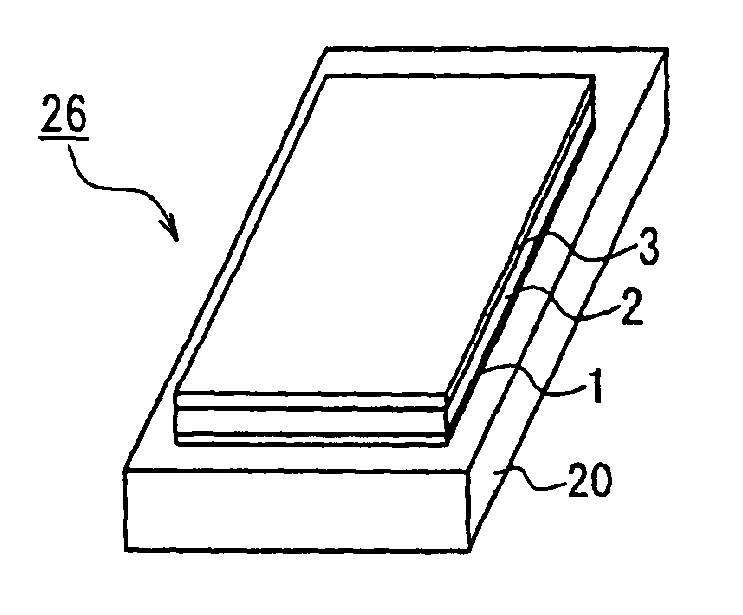
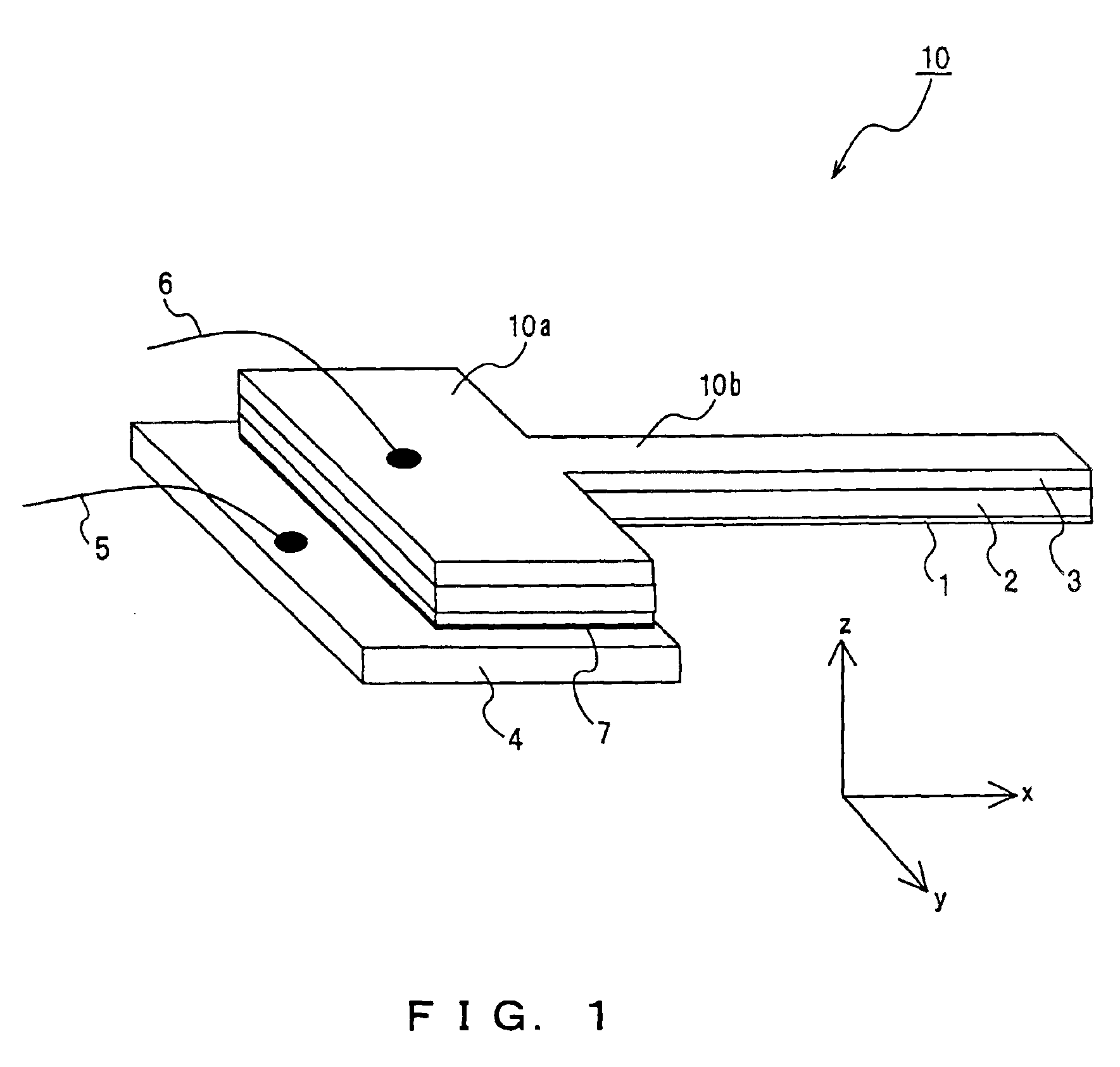
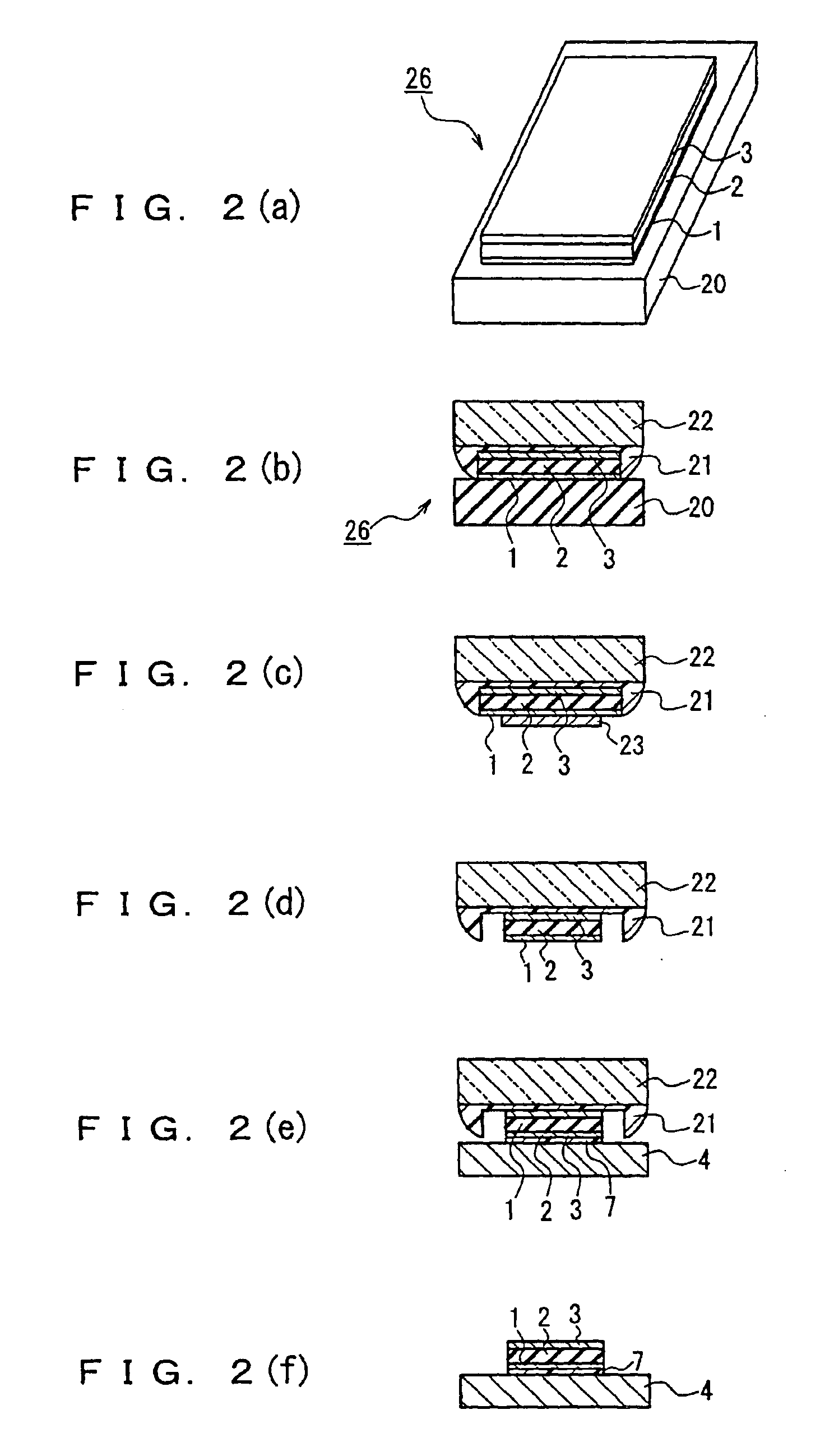
[0033]FIG. 1 is a perspective view showing a piezoelectric element of Embodiment 1 of the present invention. As shown in FIG. 1, a piezoelectric element 10 of this embodiment is formed as a T-shaped flat plate having a length of 800 μm and a thickness of 4.1 μm. An end portion 10a (with a length of 300 μm) of the piezoelectric element 10 is wider than the other portion 10b (with a length of 500 μm). The end portion 10a has a width of 500 μm, and the other portion 10b has a width of 50 μm. The end portion 10a may be fixed to a conductive substrate (stainless substrate) 4 with a conductive adhesive (silver paste) 7, thereby forming a cantilever.

[0034]The piezoelectric element 10 may include a 0.1 μm-thick platinum lower electrode 1, a 2.5 μm-thick piezoelectric thin film 2 formed on the lower electrode 1, and a 1.5 μm-thick aluminum upper electrode 3 formed on the piezoelectric thin film 2. There is electrical continuity between the lower electrode 1 and the conductive substrate 4, an...

embodiment 2

[0056]An ink jet head using a piezoelectric thin film of the present invention will be described below.

[0057]FIG. 6 schematically shows the configuration of an ink jet head of Embodiment 2 of the present invention. As shown in FIG. 6, an ink jet head 201 of this embodiment includes ten ink discharge elements 202 that are the same in shape and arranged in a row, and a drive source element 203 that is connected to the electrode of each of the ink discharge elements 202 to drive them.

[0058]FIG. 7 is a partially cutaway exploded view in perspective of an ink discharge element for an ink jet head of Embodiment 2. In the ink discharge element 202 shown in FIG. 7, A represents a pressure chamber component having a pressure chamber opening 31. B represents an actuator that is arranged to cover the top (in the form of an ellipse with a minor axis of 200 μm and a major axis of 400 μm) of the pressure chamber opening 31. C represents a liquid ink passage component that is arranged to cover the...

embodiment 3

[0061]An ink jet recording apparatus including an ink jet head of the present invention will be described below.

[0062]FIG. 9 is a perspective view schematically showing the whole of an ink jet recording apparatus of Embodiment 3 of the present invention. As shown in FIG. 9, an ink jet recording apparatus 51 of this embodiment includes the ink jet head 201 of Embodiment 2 that uses the piezoelectric effect of a piezoelectric thin film for recording. The ink drops discharged from the ink jet head 201 strike a recording medium 52 such as a paper, so that information can be recorded on the recording medium 52. A carriage 54 is attached slidably to a carriage shaft 53 that is arranged parallel to a main scanning direction (indicated by X in FIG. 9), and the ink jet head 201 is mounted on the carriage 54. As the carriage 54 goes backward and forward along the carriage shaft 53, the ink jet head 201 moves in the main scanning direction X. The ink jet recording apparatus 51 further includes...


PUM

PropertyMeasurementUnit
diameteraaaaaaaaaa
thicknessaaaaaaaaaa
thicknessaaaaaaaaaa

Abstract

A piezoelectric thin film can achieve a large piezoelectric displacement. A chemical composition of the piezoelectric thin film is expressed by Pb1+a(ZrxTi1−x)O3+a(0.2≦a≦0.6 and 0.50≦x≦0.62). The crystal structure of the piezoelectric thin film is a mixture of a perovskite columnar crystal region (24) having an ionic defect in which a portion of the constitutive elements of an oxygen ion, a titanium ion, and a zirconium ion is missing and a perovskite columnar crystal region (25) of stoichiometric composition having no ionic defect. This configuration allows a residual compressive stress in the crystal to be relaxed by the perovskite columnar crystal region (24) having an ionic defect, thus achieving a large piezoelectric displacement (displacement amount).

Description

TECHNICAL FIELD[0001]The present invention relates to a piezoelectric thin film used in a micropump, a microspeaker, an ink jet head, etc., a method for manufacturing the piezoelectric thin film, a piezoelectric element including the piezoelectric thin film, an ink jet head including the piezoelectric element, and an ink jet recording apparatus including the ink jet head.BACKGROUND ART[0002]A piezoelectric material can make mechanical-to-electrical energy conversion or electrical-to-mechanical energy conversion. Examples of the typical piezoelectric material include lead zirconate titanate (Pb(Zr, Ti)O3) (also referred to as “PZT” in the following). Particularly, PZT having a perovskite-type tetragonal crystal structure can achieve the largest piezoelectric displacement in a c-axis (<001> axis) direction. However, most piezoelectric materials are a polycrystalline material composed of aggregates of crystal grains whose crystal axes are oriented variously. Therefore, the sponta...

Claims


Application Information

Patent Timeline
Patent Type & Authority Patents(United States)
IPC IPC(8): B41J2/45B41J2/135B41J2/14C01G25/00H01L41/09H01L41/187H01L41/316H01L41/39
CPCC01G25/006H01L41/316H01L41/1876H01L41/094C01P2002/34H10N30/2042H10N30/8554H10N30/076C23C14/08
Inventor TORII, HIDEOKAMADA, TAKESHIKANNO, ISAKUTAKAYAMA, RYOICHI
Owner PANASONIC CORP
Why Eureka
Try Eureka