

Encoded excitation source Raman spectroscopy methods and systems
a raman spectroscopy and excitation source technology, applied in the field oframan spectroscopy, can solve the problems of obscuring the raman portion of the spectrum, serds may not sufficiently reduce fluorescence and stray light in all environments, and raman spectroscopy may be more difficult in diffuse media such as biological tissu
- Summary
- Abstract
- Description
- Claims
- Application Information
AI Technical Summary
Benefits of technology
Problems solved by technology
Method used
Image

Examples
example 1
Raman Molecular Response Calculation
[0039]A spectral impulse response can be used to make a mathematical distinction between a non-Raman signal (e.g., the component of a spectrum that can be attributed to non-Raman scattering) and the Raman signal (e.g., the component of a spectrum that can be attributed to Raman scattering). Both spectral components may include sub-components that are linear and non-linear with respect to the exciting wavelengths. However, the linear components are generally stronger than the non-linear components. The linear terms can be described by an impulse response. The non-Raman spectrum, SNR, generated by a linear transformation of the exciting intensity can be expressed as follows:
SNR(ν,t)=∫hNR(ν,ν′)Se(ν′,t)dν′ (1)
where Se(ν, t) is the exciting signal as a function of optical output frequency ν and the slow time t; hNR is the non-Raman impulse response and ν′ is an exciting frequency. The distinguishing feature of the Raman and the non-Raman signals is th...
example 2
Raman Signal Discrimination Using Coded Illumination
[0040]The structural difference between the Raman and non-Raman impulse responses described in Example 1 can be used to isolate the signals from each other. Specifically, the Raman impulse response can be determined from measurements of the total spectrum. To achieve this, the excitation signal is temporally and spectrally encoded and the total spectrum or multiplex measurements derived from the spectrum are digitally processed. The excitation beam can be selected from a combination from three or more light excitation wavelengths, and multi-wavelength excitation beams including two or more wavelengths of light can be used. The exciting spectrum can be constrained by the fact that Se(ν, t) is a positively valued function, but temporal modulation and adaptation of the exciting spectrum can effectively create bipolar or complex codes.
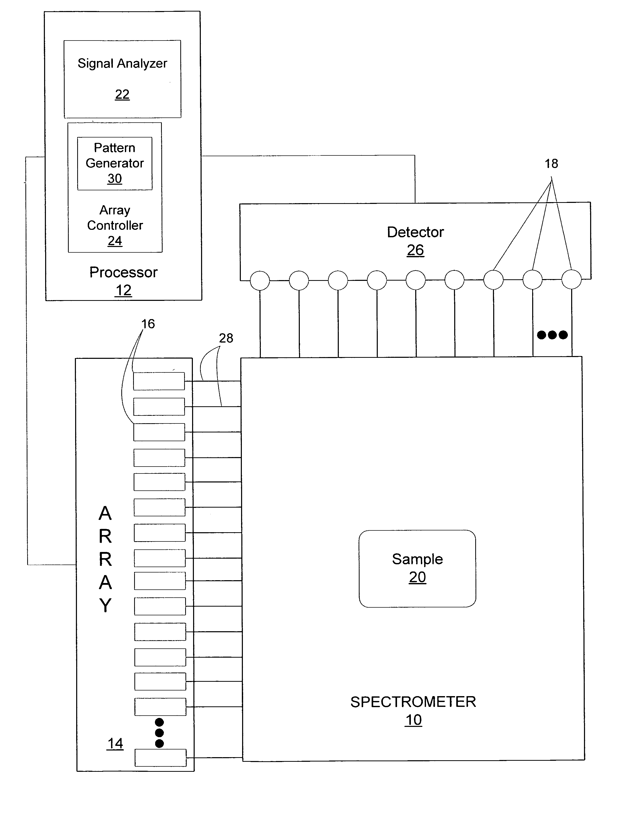
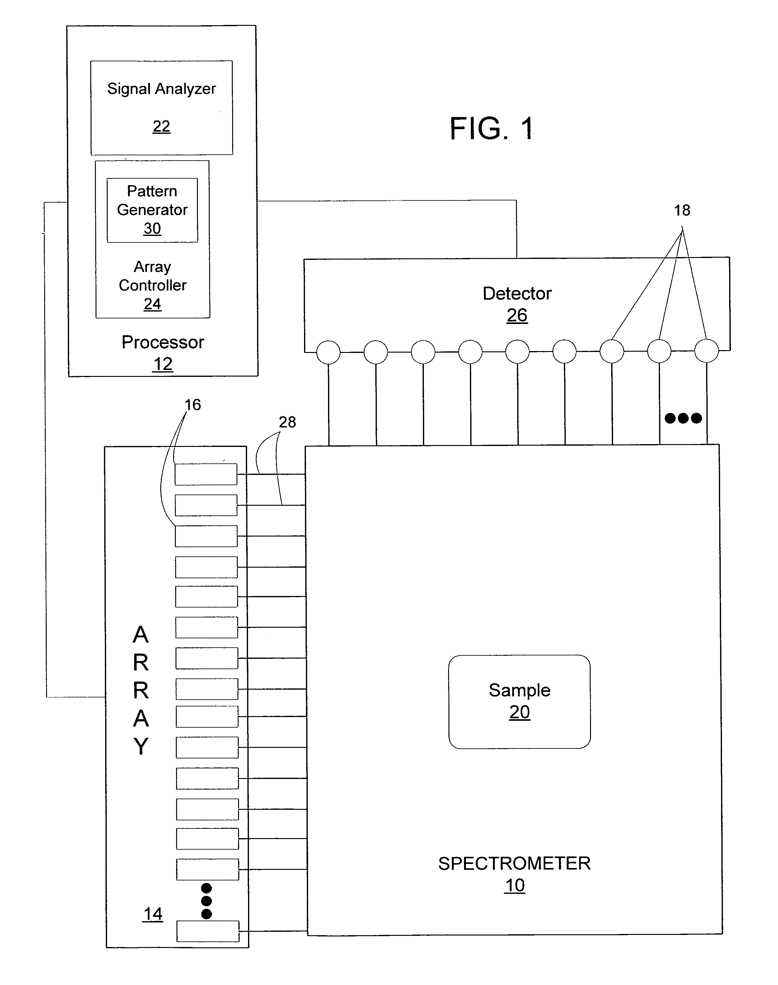
[0041]An array of individually laser sources that can be modulated can be used to implement a coded Ra...
example 3
Illumination Code
[0045]The total spectrum may be defined as follows: S=[SNRSR](13)
[0046]The measurement response matrix may be defined as follows: F=[F11F21F12F22⋮⋮F1NtF2Nt](14)
Equation (10) can be expressed as follows:
m=FS (15)
If it is assumed that only one spectral component is active in each illumination time step, F1,nt is an Nν×Nν identity matrix and F2,Nt is an Nν×Nν triangular matrix with one non-zero off center diagonal. For example, if Nν=3 and the excitation signal consists of two exposures with the second exposure shifted from the first by one frequency bin, then F=[100100010010001001100000010100001010](16)
[0047]Equation (15) can be inverted to estimate S using a least squares estimator.
[0048]As an example of coded illumination Raman spectroscopy, spectra from low concentrations of dextrose in water in a quartz cuvette were obtained. Each spectrum was obtained using a single excitation wavelength. The illumination wavelengths in this example are as follows: λ1=827.03...
PUM
| Property | Measurement | Unit |
|---|---|---|
| full width at half maximum | aaaaa | aaaaa |
| Raman spectroscopy | aaaaa | aaaaa |
| light excitation wavelengths | aaaaa | aaaaa |
Abstract
Description
Claims
Application Information