
Electrophoretic particles, and processes for the production thereof

a technology of electrophoretic particles and electrophoretic particles, applied in the field of electrophoretic particles, can solve the problems of rapid white state degradation, widespread use of these displays, and inadequate service life of these displays

Inactive Publication Date: 2006-02-21
E INK CORPORATION
View PDF446 Cites 868 Cited by
  • Summary
  • Abstract
  • Description
  • Claims
  • Application Information

AI Technical Summary

Benefits of technology

This patent describes an electrophoretic medium that includes at least one electrically charged particle suspended in a suspending fluid and capable of moving through the fluid when an electric field is applied. The at least one particle is made of copper chromite, which is coated with a polymer that can be chemically bonded to the particle. The polymer coating can be made of silica or a polymer chemically bonded to the particle. The electrophoretic medium can also include other particles with different optical characteristics and electrophoretic mobility. The electrophoretic display can be made with encapsulated or polymer-dispersed particles. The invention also provides a process for producing a polymer-coated copper chromite particle. The technical effects of this patent include improved stability and functionality of the electrophoretic medium, as well as improved display quality and performance.

Problems solved by technology

Nevertheless, problems with the long-term image quality of electrophoretic displays have prevented their widespread usage.
For example, particles that make up electrophoretic displays tend to settle, resulting in inadequate service-life for these displays.
Among the remaining problems of encapsulated electrophoretic displays are so-called “rapid white state degradation”, a relatively rapid decline in the reflectivity of the white optical state of the display during the first few days of operation.
Another problem, which is discussed in detail in the aforementioned 2003 / 0137521 and WO 03 / 107315, is so-called “dwell state dependency”, which causes the change in optical state of an electrophoretic medium produced by a specific waveform to vary depending upon the time for which the electrophoretic medium has been in a particular optical state before the waveform is applied.
However, the present inventors and their co-workers have discovered that the aforementioned problems with prior art electrophoretic displays are associated with the use of carbon black for the black electrophoretic particles.
Carbon black has a complex and poorly understood surface chemistry, which may vary widely with the specific raw material (typically petroleum) and the exact process used for the carbon black production.
Hence, it is difficult to ensure consistent surface properties of carbon black from batch to batch.
This is especially problematic in electrophoretic displays, since the electrophoretic particles used are typically so small (of the order of 1 μm) that their properties are dominated by the properties of their surfaces.
It has also been discovered (although this information is not disclosed in the prior art) that carbon black presents certain peculiar difficulties in obtaining proper charging of particles in opposite charge dual particle electrophoretic displays.
The resultant mixture of negatively and positively charged titania particles leads to contamination of the extreme optical states of the medium, thus adversely affecting its contrast ratio.
While this does not affect the operation of the display itself, it does complicate the manufacture of encapsulated dual particle displays.
Also, when such an electrophoretic medium is produced by coating capsules on to a substrate, it is desirable that the exposed surface of the capsule layer be reasonably flat, since otherwise difficulties may be encountered in laminating the capsule layer to other layers in the final display.
The low density of carbon black, coupled with the small concentration at which it is used in most electrophoretic media, lead to capsule densities close to that of water, hindering the sorting process.
However, the search for such a black particle is subject to considerable difficulties.
The pigment particles must also be able to sustain a charge when suspended in the suspending fluid, and the zeta potentials of the particles caused by such charges should all be of the same polarity and should not extend over an excessively wide range, or the electrophoretic medium may not have desirable electro-optic properties; for example, if some particles have very low zeta potentials, a very long driving pulse may be required to move such particles to a desired position within the electrophoretic medium, resulting in slow switching of the medium.
It will be appreciated that such information relating to the ability of pigment particles to acquire and hold charges is not available for most pigments potentially usable in an electrophoretic display, since such electrical properties are irrelevant to the normal commercial uses of the pigments.

Method used

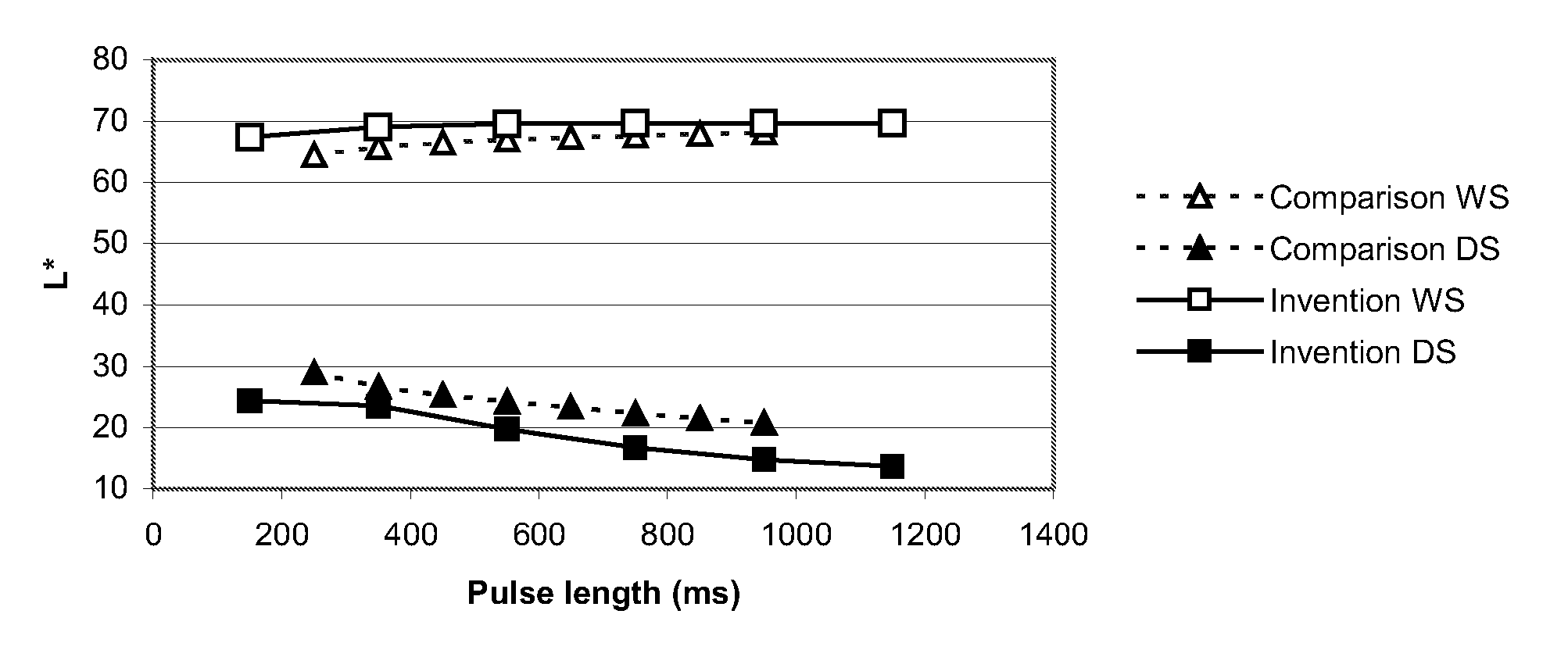
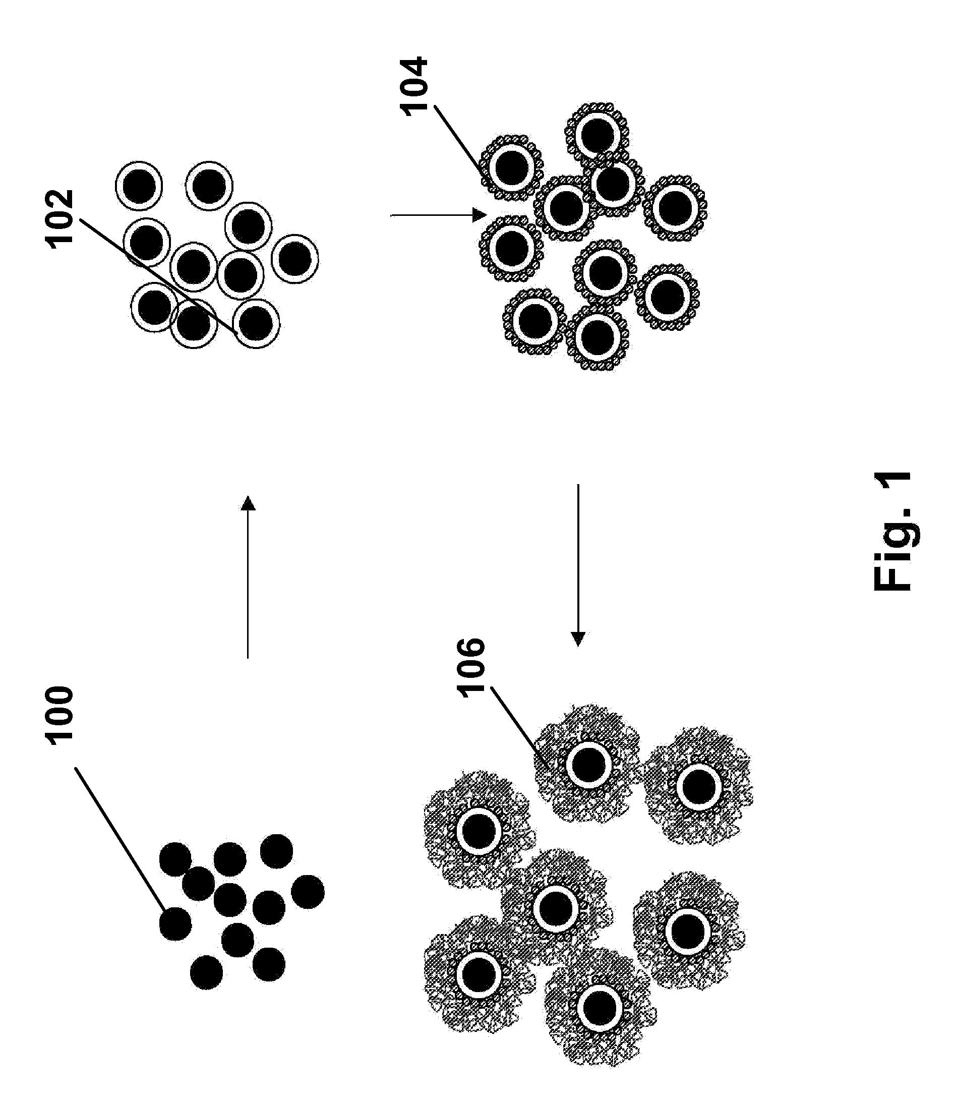
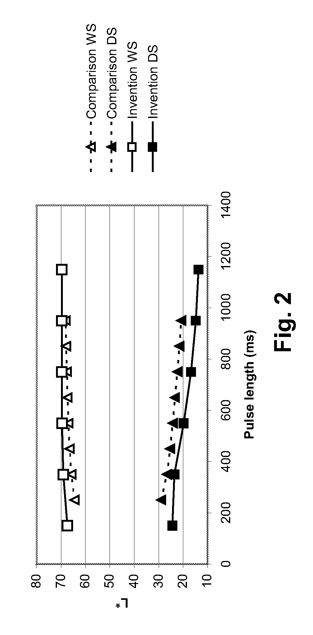

Image

  • Electrophoretic particles, and processes for the production thereof
  • Electrophoretic particles, and processes for the production thereof
  • Electrophoretic particles, and processes for the production thereof

Examples


example 1

Silica Coating of Copper Chromite Pigment

[0048]A dispersion was prepared consisting of Shepherd Black 1G (50 g), water (420 mL) and sodium silicate solution (6 mL of a solution containing approximately 14% of sodium hydroxide and 27% of silica, available from Aldrich Chemical Company); the dispersion was sonicated for one hour. The dispersion was then added to a 1 L three-necked flask equipped with a stirring bar, reflux condenser (open to the air) and two addition funnels equipped with needle-valve control stopcocks. The flask was partially immersed in a silicone oil bath and heated to 100° C. with rapid stirring over a period of one hour. During this heating period, the first addition funnel was charged with 0.22M sulfuric acid (150 mL) and the second with a mixture of the aforementioned sodium silicate solution (11 mL) and water (70 mL). After the silicone oil bath reached 100° C., the two solutions in the addition funnels were simultaneously added to the dispersion in the flask ...

example 2

Silane Treatment of Silicated Copper Chromate Pigment

[0049]The silica-coated copper chromite pigment produced in Example 1 was used without further treatment in a silanization process. For this purpose, a mixture of 300 ml of ethanol, 30 ml of water and 40 g of a 40 weight percent solution of N-[3-(trimethoxysilyl)propyl]-N′-(4-vinylbenzyl)ethylenediamine hydrochloride (available from United Chemical Technologies, 2731 Bartram Road, Bristol, Pa. 19007-6893) in methanol was stirred rapidly for 7 minutes, the pigment was added thereto, and the resultant mixture was stirred for a further 5 minutes. The resultant suspension was poured into plastic bottles and centrifuged at 3500 rpm for 30 minutes. The supernatant liquor was decanted, and the silanized pigment redispersed in ethanol and centrifuged at 3500 rpm for 30 minutes, and the liquid decanted. The washing was repeated, and the pigment finally dried in air for 18 hours, then under vacuum at 70° C. for 2 hours. The amount of surfac...

example 3

Polymer Coating of Silanized Copper Chromate Pigment

[0050]The silanized pigment produced in Example 2 (50 g) was placed in a round-bottomed flask with toluene (50 g) and 2-ethylhexyl methacrylate monomer (50 g). The resultant mixture was stirred rapidly under a nitrogen atmosphere (argon may alternatively be used) for 20 minutes, then slowly heated to 50° C. and AIBN (0.5 g in 10 ml of toluene) added quickly. The suspension was then heated to 65° C. and stirred at this temperature under nitrogen for a further 18 hours. The resultant suspension was poured into plastic bottles, the flask being washed out with ethyl acetate to remove residual product and the ethyl acetate solution added to the bottles. The bottles were centrifuged at 3500 rpm for 30 minutes. The supernatant liquor was decanted, and the polymer-coated pigment re-dispersed in ethyl acetate and centrifuged at 3500 rpm for 30 minutes, and the liquid decanted. The washing was repeated, and the pigment dried in air until a w...


PUM

PropertyMeasurementUnit
diameteraaaaaaaaaa
average diameteraaaaaaaaaa
mean diameteraaaaaaaaaa

Abstract

Copper chromite particles can advantageously be used as black particles in electrophoretic media and displays. Preferably, the copper chromite particles are coated with a silica coating and a polymer coating.

Description

CROSS REFERENCE TO RELATED APPLICATIONS[0001]This application is a continuation-in-part of application Ser. No. 09 / 140,846, filed Aug. 28, 1998 (now U.S. Pat. No. 6,727,881), which in turn claims benefit of (1) application Ser. No. 60 / 057,133, filed Aug. 28, 1997; (2) application Ser. No. 60 / 057,716, filed Aug. 28, 1997; (3) application Ser. No. 60 / 057,799, filed Aug. 28, 1997; (4) application Ser. No. 60 / 057,163, filed Aug. 28, 1997; (5) application Ser. No. 60 / 057,122, filed Aug. 28, 1997; (6) application Ser. No. 60 / 057,798, filed Aug. 28, 1997; (7) U.S. Ser. No. 60 / 057,118, filed Aug. 28, 1997; (8) application Ser. No. 60 / 059,543, filed Sep. 19, 1997; (9) application Ser. No. 60 / 059,3 58, filed Sep. 19, 1997; (10) application Ser. No. 60 / 065,630, filed Nov. 18, 1997; (11) application Ser. No. 60 / 065,605, filed Nov. 18, 1997; (12) application Ser. No. 60 / 065,629, filed Nov. 18, 1997; (13) application Ser. No. 60 / 066,147, filed Nov. 19, 1997; (14) application Ser. No. 60 / 066,245, ...

Claims


Application Information

Patent Timeline
Patent Type & Authority Patents(United States)
IPC IPC(8): G02B26/00G03G17/04G09G3/34B41J3/407C09B67/08C09C1/00C09C1/24C09C1/34C09C3/00C09C3/10C09C3/12G02B26/02G02F1/133G02F1/1333G02F1/1334G02F1/1343G02F1/1345G02F1/135G02F1/1365G02F1/167G04G21/04G06F3/14G06F3/147G09F9/302G09F9/37H01L27/12H10K99/00
CPCG03G17/02G02F1/167G03G17/06G03G17/04G02F2001/1678B41J3/4076B82Y10/00B82Y30/00C09C3/006C09C3/10C09C3/12C09B67/0013C09C1/00C09C1/34G02F1/133305G02F1/133348G02F1/13336G02F1/1334G02F1/1343G02F1/1345G02F1/135G02F1/1365G02F1/172G02B26/026G09F9/302G09F9/372G06K19/07703H01L27/12C01P2002/88C01P2004/32C01P2004/51C01P2004/61C01P2004/62C01P2004/64C01P2004/82C01P2004/84C01P2006/10C01P2006/12C01P2006/40C01P2006/60C01P2006/80C01P2006/90G02F2202/12G02F2202/28C25D13/02Y10T428/2991Y10T428/2998C09B67/0097C23C18/1212C23C18/1229C23C18/1295H10K85/114H10K85/20H10K85/113H10K85/611H10K85/60H10K85/615H10K85/311H10K85/30H10K10/462H10K10/466H10K19/00
Inventor PULLEN, ANTHONY EDWARDWHITESIDES, THOMAS H.HONEYMAN, CHARLES H.COMISKEY, BARRETTALBERT, JONATHAN D.
Owner E INK CORPORATION
Learn More