Carbon dioxide sensor

a carbon dioxide sensor and sensor technology, applied in the field of carbon dioxide sensors, can solve the problems of difficult to monitor only the concentration of carbon dioxide, carbon dioxide sensor is susceptible to humidity, and the carbon dioxide sensor is not widely used, so as to reduce the influence of humidity

Inactive Publication Date: 2006-02-28
TDK CORPARATION
View PDF22 Cites 3 Cited by
  • Summary
  • Abstract
  • Description
  • Claims
  • Application Information

AI Technical Summary

Benefits of technology

[0011]The present invention has been achieved in view of the above problems. It is an object of the invention to provide a carbon dioxide sensor which is operatable at room temperature and reduce the influence of humidity.

Problems solved by technology

However, this carbon dioxide sensor is not widely used because of the size and the cost of the apparatus.
In addition, a carbon dioxide sensor using a semiconductor has been also in practical use; however, it is difficult to monitor only the carbon dioxide concentration due to poor carbon dioxide selectivity.
However, there has been a problem that this carbon dioxide sensor is susceptible to humidity, because the metal carbonate is used as the detection electrode.
The operation temperature of the carbon dioxide sensor is as high as 400° C. to 700° C., so the overall power consumption of the sensor is high and there has been a problem that the heat deterioration of materials occur.
This affects subtly on the environment for monitoring, which is a problem.
However, the carbon dioxide sensor using the tin oxide semiconductor as the detection electrode requires four or more minutes for response and the difficulty of prompt measurement has been a problem.
In addition, there has been another problem that the response time or sensitivity varies by humidity because water vapor is involved in the detection mechanism in this carbon dioxide sensor.
Also, the carbon dioxide sensor using the metal oxide is susceptible to humidity.
Although the influence of humidity on the sensitivity is small, the absolute value of the electromotive force output varies and the correction is required according to humidity, which is a problem.

Method used


Image

  • Carbon dioxide sensor
  • Carbon dioxide sensor
  • Carbon dioxide sensor

Examples


first embodiment

[First Embodiment]

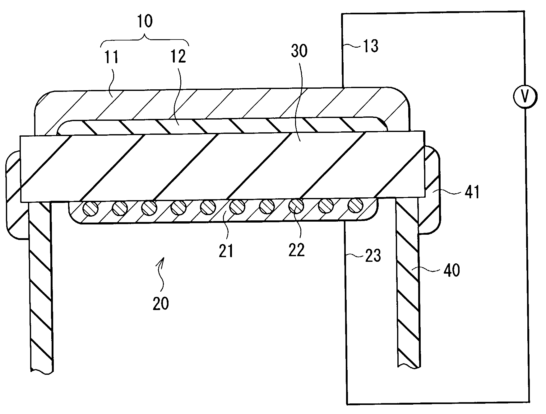
[0030]FIG. 1 shows a configuration of a carbon dioxide sensor according to a first embodiment of the invention. In the carbon dioxide sensor, a detection electrode 10 is placed on the opposite side of a counter electrode 20 sandwiching an electrolyte 30 in between. The detection electrode 10 and counter electrode 20 are connected to a potentiometer by leads 13 and 23. A quartz glass tube 40 is attached with an adhesive layer 41 on the electrolyte 30 for preventing the counter electrode 20 to be exposed in the measurement atmosphere.

[0031]The detection electrode 10 comprises a metal oxide layer 11 including metal oxide and a metal carbonate layer 12 including metal carbonate. The metal carbonate layer 12 is placed between the metal oxide layer 11 and the electrolyte 30. With such a layer structure, the influence of humidity can be decreased and the carbon dioxide sensing property can be improved. Preferably, the thicknesses of the metal oxide layer 11 and the metal ...

second embodiment

[Second Embodiment]

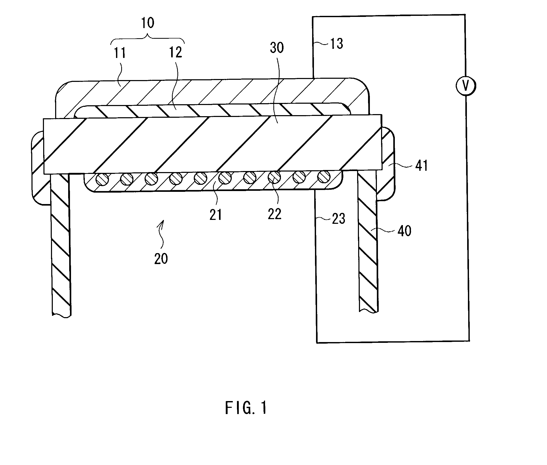
[0053]FIG. 2 shows the configuration of a carbon dioxide sensor according to a second embodiment of the invention. In the carbon dioxide sensor, a detection electrode 50 and a counter electrode 60 are placed on the same side of an electrolyte 70. The detection electrode 50 and a counter electrode 60 are connected to a potentiometer by leads. The detection electrode 50 may be placed on the opposite side of the counter electrode 60 sandwiching the electrolyte 70 in between, as shown in FIG. 1; however, with this configuration, that is, the detection electrode 50 and the counter electrode 60 are placed on the same surface of the electrolyte 70, it facilitate the extraction of the leads and the manufacturing process. In addition, the miniaturization of device can be improved, which is preferable.

[0054]The detection electrode 50 has a thickness of, for example 0.1 μm to 100 μm and contains the metal oxide and the metal carbonate including plural components. The metal o...

third embodiment

[Third Embodiment]

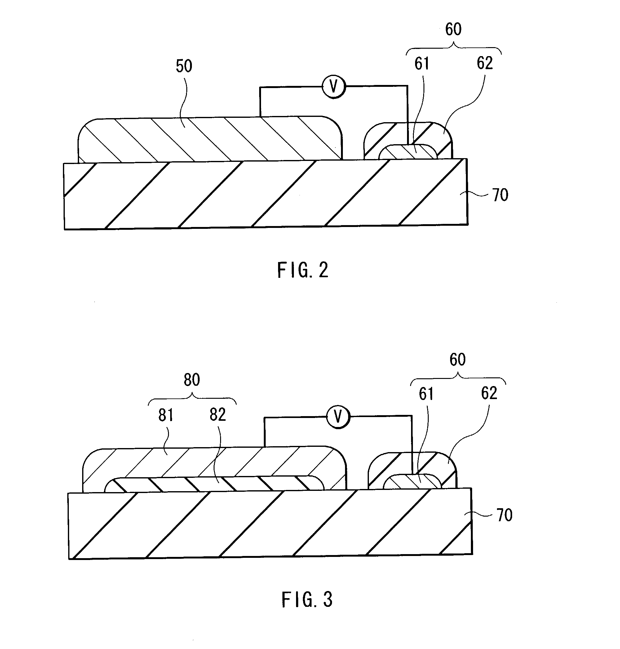
[0074]FIG. 3 shows the configuration of a carbon dioxide sensor according to a third embodiment of the invention. The carbon dioxide sensor has the same configuration as that of the second embodiment except that a detection electrode 80 has the layer structure as the first embodiment. Therefore, the same components are indicated by the same numerals and the detail explanation thereof will be omitted.

[0075]The detection electrode 80 comprises a metal oxide layer 81 including metal oxide, a metal carbonate layer 82 including plural components of metal carbonate. The metal carbonate layer 82 is provided between the metal oxide layer 80 and the electrolyte 70. With such a layer structure, the influence of humidity can be decreased and the carbon dioxide sensing property can be improved. Preferably, the thickness of the metal oxide layer 81 is 10 nm to 500 μm and the thickness of the metal carbonate layer 82 is 10 nm to 500 μm, for example, because higher effects can be...


PUM

PropertyMeasurementUnit
temperatureaaaaaaaaaa
thicknessesaaaaaaaaaa
grain sizeaaaaaaaaaa

Abstract

A carbon oxide sensor having high sensitivity capable of reduction of influence of humidity is provided. A detection electrode and a counter electrode are provided on one side of an electrolyte, respectively. The detection electrode contains a metal oxide and a metal carbonate including plural components. The metal carbonate preferably contains a first component of alkali metal carbonate and a second component of at least one element selected from the group consisting of alkali earth metal carbonate, transition metal carbonate, zinc carbonate, cadmium carbonate, indium carbonate, lead carbonate and bismuth carbonate. Specifically, it is preferable to contain the first component including Li2CO3 and the second component including at least one element selected from the group consisting of BaCO3, CaCO3 and SrCO3.

Description

BACKGROUND OF THE INVENTION[0001]1. Field of the Invention[0002]The present invention relates to a carbon dioxide sensor used for an indoor and outdoor environmental monitoring and control, an agro-industrial process such as greenhouse horticulture, disaster prevention, a measurement of metabolic function of body surface, and a medical care.[0003]2. Description of the Related Art[0004]In recent years, a need for carbon dioxide sensor is increasing particularly in detection of dirty air in the room caused by the spread of air conditioner, detection of contamination air in livestock facilities, control of the growth of plants in greenhouse and various industrial processes, and various kinds of carbon dioxide sensors have been reported.[0005]Specifically, an infrared absorption carbon dioxide sensor has been in practical use, for example. However, this carbon dioxide sensor is not widely used because of the size and the cost of the apparatus. In addition, a carbon dioxide sensor using ...

Claims


Application Information

Patent Timeline
Patent Type & Authority Patents(United States)
IPC IPC(8): G01N19/00G01N33/00G06F19/00
CPCG01N33/004Y02A50/20
Inventor ONO, SHIZUKOSHIBUE, AKIRAYAMAZOE, NOBORUSHIMANOE, KENGOOBATA, KENJIMIURA, NORIO
Owner TDK CORPARATION
Why Eureka
Try Eureka