Commercial fischer-tropsch reactor

a fischertropsch reactor and commercial technology, applied in the direction of physical/chemical process catalysts, metal/metal-oxide/metal-hydroxide catalysts, gas-gas reaction processes, etc., can solve the problems of decreasing the overall conversion and volume productivity transportation presents technological challenges, and natural occurring sources of crude oil used for liquid fuels such as gasoline and middle distillates, etc., to achieve high overall conversion and volume productivity

Inactive Publication Date: 2006-03-14
CONOCOPHILLIPS CO
View PDF18 Cites 28 Cited by
  • Summary
  • Abstract
  • Description
  • Claims
  • Application Information

AI Technical Summary

Benefits of technology

[0014]The present invention provides improved efficiency over prior art systems and avoids the difficulties of the prior art. In particular, the present system provides a fixed-bed Fischer Tropsch reactor system that achieves high overall conversion and volume productivity through the optimization of several parameters, including inlet temperatures, coolant temperature, length of catalyst bed, and heat transfer area and coefficient. The present system also includes an embodiment in which the catalyst loading is varied along the length of the reactor so as to further optimize reactor operation.

Problems solved by technology

Wells that provide natural gas are often remote from locations with a demand for the consumption of the natural gas.
This transportation presents technological challenges due in part to the large volume occupied by a gas.
However, this contributes to the final cost of the natural gas and is not economical
Further, naturally occurring sources of crude oil used for liquid fuels such as gasoline and middle distillates have been decreasing and supplies are not expected to meet demand in the coming years.
Iron has the advantage of being readily available and relatively inexpensive but also has the disadvantage of greater water-gas shift activity.
Ruthenium is highly active but quite expensive.
On the other hand, because the desired liquid products are mixed with the suspending liquid, recovery of the liquid products can be relatively difficult.
This difficulty is compounded by the tendency of the catalyst particles to erode in the slurry, forming fine catalyst particles that are also relatively difficult to separate from the liquid products.
Fixed bed reactors avoid the problems of liquid separation and catalyst separation, but do not provide the mixing of phases that allows good thermal control in slurry bubble column reactors.
Because the Fischer Tropsch reaction is exothermic, however, a thermal gradient tends to form along the length of the reactor, with the temperature increasing with distance from the reactor inlet.
In addition, for most Fischer Tropsch catalyst systems each ten degree rise in temperature increases the reaction rate approximately 60%, which in turn results in the generation of still more heat.
Thus, for a given reactor system having a known amount of catalyst with a certain specific activity and known coolant temperature, the maximum flow rate of reactants through the reactor is limited by the need to maintain the catalyst below a predetermined maximum catalyst temperature at all points along the length of the catalyst bed and the need to avoid thermal runaway which can result in catalyst deactivation and possible damage to the physical integrity of the reactor system.
The net result is that it is unavoidable to operate most of the reactor at temperatures below the maximum temperature, with the corresponding low volumetric productivities over most of the reactor volume.
Prior art systems constrained by these considerations typically achieve less than optimal results.
In particular, conventional systems typically fail to achieve maximum productivity for a given reactor volume.

Method used


Image

  • Commercial fischer-tropsch reactor
  • Commercial fischer-tropsch reactor
  • Commercial fischer-tropsch reactor

Examples


example i

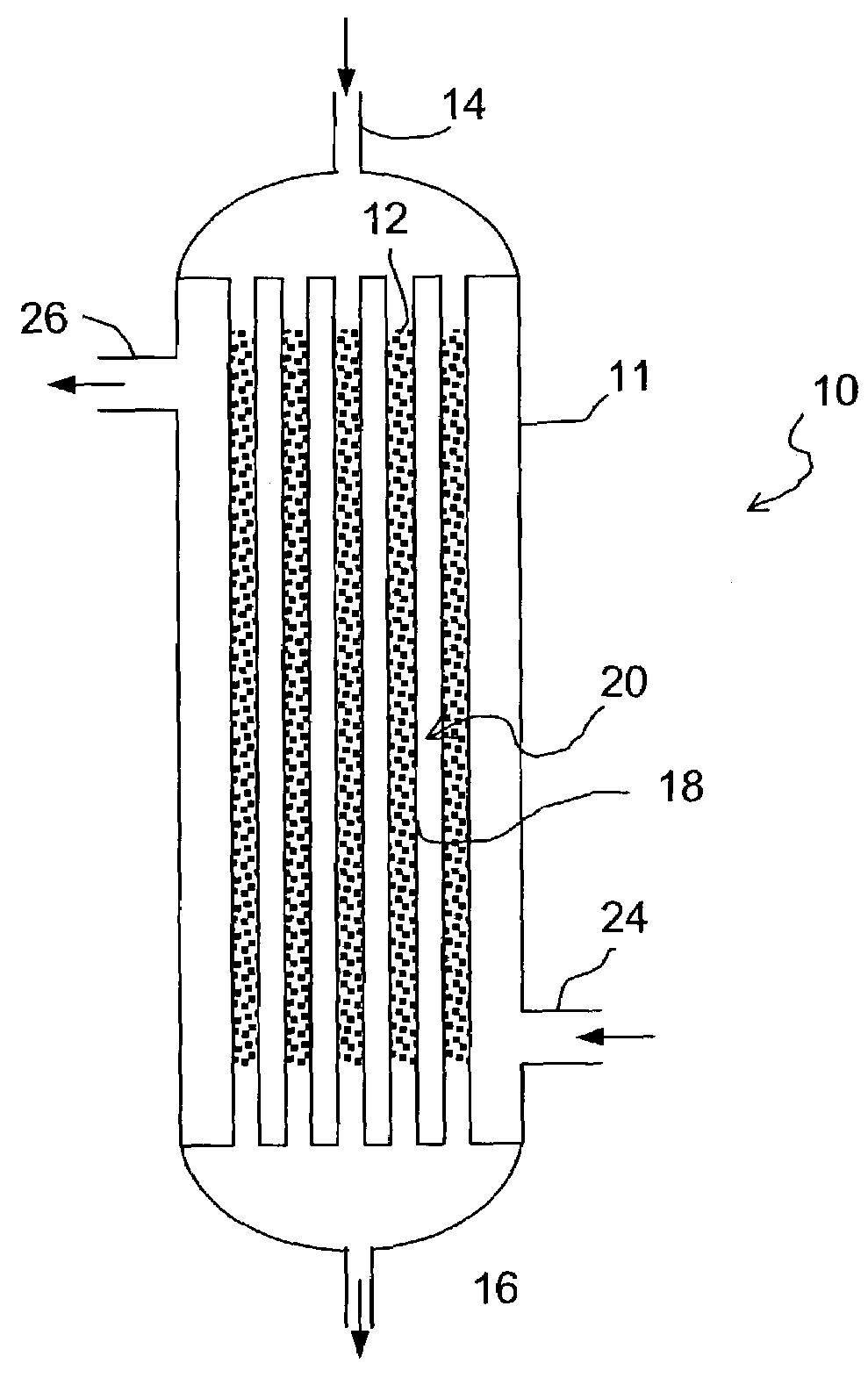
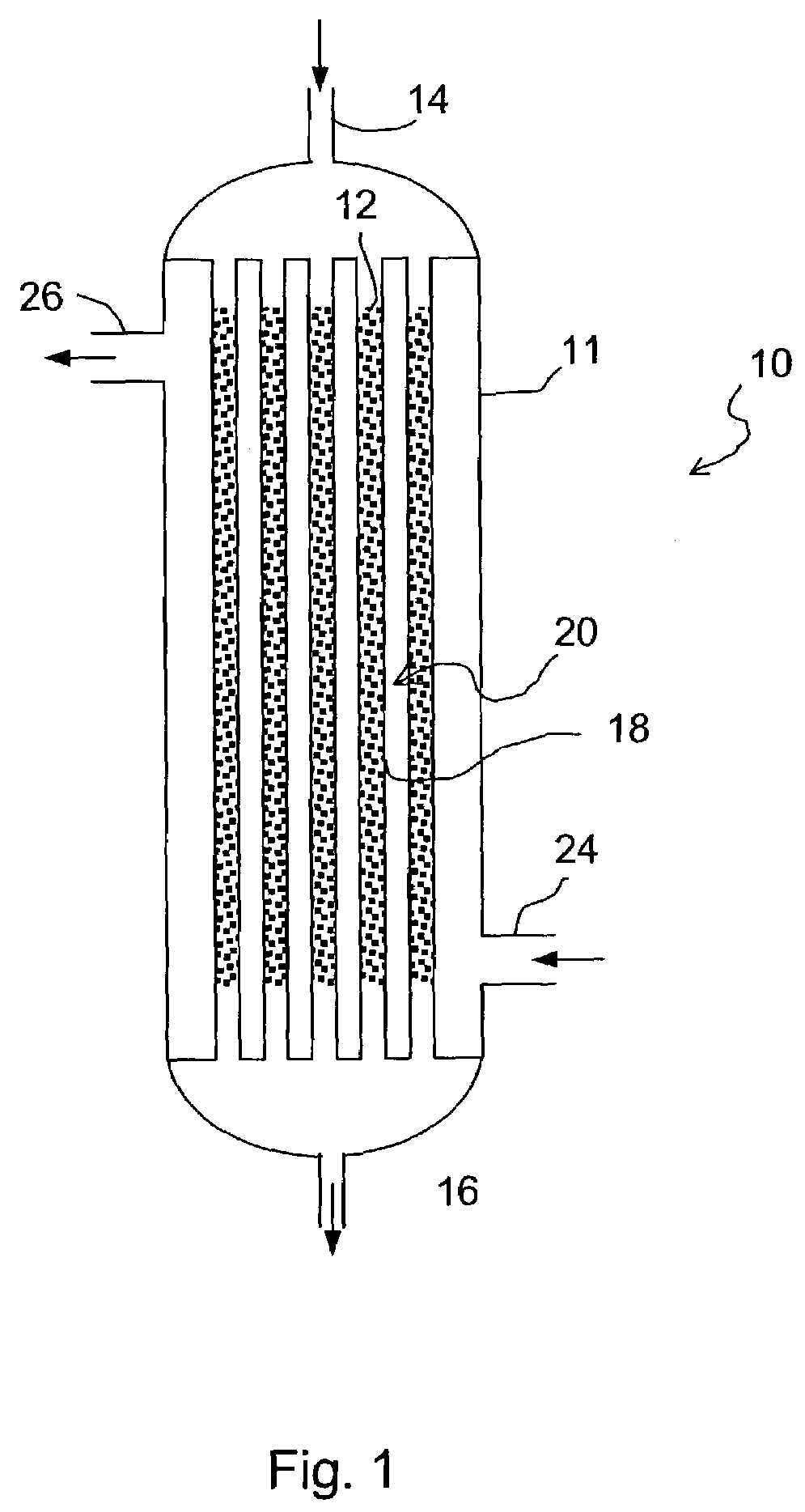
[0036]A reactor constructed in accordance with the present invention was modeled using the following parameters:

[0037]

superficial gas velocity:22.8 cm / sH2 / CO at inlet:2N2 mole fraction at inlet:8.3%inlet temperature:215° C.cooling side temperature:215° C.operating pressure:400 psigsuperficial velocity of circulating liquid:0.01 m / s

Using these parameters, the maximum uniform catalyst loading allowed by the model while still avoiding temperature runaway was 2.4 times the maximum loading allowed for a model of a conventional reactor system operating under the same conditions.

[0038]Based on modeling data, it is believed that a Fischer-Tropsch reactor system according to this invention can have a hydrocarbon productivity such that the yield of hydrocarbons in each tube in the reactor is greater than 100 (kg hydrocarbons) / hr / (m3 reaction zone) and more preferably is greater than 150 (kg hydrocarbons) / hr / (m3 reaction zone).

[0039]As mentioned above, in some instances the optimum reactor per...


PUM

PropertyMeasurementUnit
heightaaaaaaaaaa
heightaaaaaaaaaa
superficial velocityaaaaaaaaaa

Abstract

A process for producing hydrocarbons comprises providing a multi-tubular reactor having at least 100 tubes units containing a catalyst, each tube being between 2 and 5 meters tall and in thermal contact with a cooling fluid; feeding hydrogen and carbon monoxide to each tube at a linear gas superficial velocity less than about 60 cm/s; and converting the gas feedstream to hydrocarbons on the catalyst, wherein the yield of hydrocarbons in each tube is greater than 100 (kg hydrocarbons)/hr/(m3 reaction zone). Each tube may have an internal diameter greater than 2 centimeters. The catalyst may be active for Fischer Tropsch synthesis and may comprise cobalt or iron. The maximum difference in the radially-averaged temperature between two points that are axially spaced along the reactor is less than 15° C., preferably less than 10° C. The catalyst loading or intrinsic activity may vary along the length of the reactor.

Description

CROSS-REFERENCE TO RELATED APPLICATIONS[0001]Not applicable.STATEMENT REGARDING FEDERALLY SPONSORED RESEARCH OR DEVELOPMENT[0002]Not applicable.TECHNICAL FIELD OF THE INVENTION[0003]Natural gas, found in deposits in the earth, is an abundant energy resource. For example, natural gas commonly serves as a fuel for heating, cooking, and power generation, among other things. The process of obtaining natural gas from an earth formation typically includes drilling a well into the formation. Wells that provide natural gas are often remote from locations with a demand for the consumption of the natural gas.[0004]Thus, natural gas is conventionally transported large distances from the wellhead to commercial destinations in pipelines. This transportation presents technological challenges due in part to the large volume occupied by a gas. Because the volume of a gas is so much greater than the volume of a liquid containing the same number of gas molecules, the process of transporting natural g...

Claims


Application Information

Patent Timeline
Patent Type & Authority Patents(United States)
IPC IPC(8): C07C27/00B01J8/06B01J12/00B01J23/745B01J23/75C10G2/00
CPCB01J8/06B01J8/067B01J12/00C10G2/341B01J23/745B01J2208/00053B01J2208/00061B01J2208/00097B01J2208/00212B01J23/75
Inventor ESPINOZA, RAFAEL L.ZHANG, JIANPINGWRIGHT, HAROLD A.HARKINS, TODD H.
Owner CONOCOPHILLIPS CO
Why Eureka
Try Eureka