Method of assembling an actuator assembly of a disk drive and of reducing torque out retention values in subsequent de-swaging

a technology of disk drive and actuator, which is applied in the field of disk drive, can solve the problems of metal debris on the surface of the disk, large damage to the disk, and cracking and metal failure, and achieve the effects of reducing the retention torque, reducing the chipping of the metal components, and enhancing the chemical vapor deposition of chf3

Inactive Publication Date: 2006-04-11
MAXTOR
View PDF7 Cites 11 Cited by
  • Summary
  • Abstract
  • Description
  • Claims
  • Application Information

AI Technical Summary

Benefits of technology

[0016]Another lubricant that provides good results is solid films, such as solid fluorocarbon films. In testing using fluorocarbon solid films, a coating having a thickness ranging from 25 to 2700 angstroms was applied to a number of swage plates by plasma enhanced chemical vapor deposition of CHF3. As with the polymer films, deswaging showed a pronounced decrease in retention torque. The testing further revealed a pronounced decrease in chipping of the metal components and improved deformation characteristics of the metal components following swaging. The use of the solid film coating also provided better uniformity in gram load throughout the head gimbal assembly. Similarly, the inventors believe a single monolayer film will provide adequate lubrication.

Problems solved by technology

Unfortunately, the swage ball can tear away metal as it is forced through the through-hole and cause cracking and metal failure.
The loose metal pieces may adhere to the perimeter of the exit side of the through-hole, like a metal burr, which may then dislodge after assembly of the drive, thereby placing metal debris on the surface of a disk.
Such debris, if it breaks away, can cause extensive damage to the disk.
If the flying characteristics of the slider are changed as a result, the flying dynamics of the slider and the overall performance of the drive may be adversely affected.
For example, testing may reveal that a transducer is not performing properly and needs replacing.
As previously described, swaging is a severe process, particularly with nickel-plated metal actuators and suspension arms.
As a result, deswaging of parts can cause damage to both the actuator arm and the boss of the suspension arm manifesting in the form of cracking and other material failures.
Such failures can contribute to undesirable contamination due to creation of particles.
Although a liquid lubricant of this type may have certain advantages in the swaging process, it is also known that isopropyl alcohol is not a very effective lubricant.
Regardless, isopropyl alcohol applied in the swaging process does not provide lubrication in later de-swaging because the alcohol will have evaporated.
Although this reference may address lubrication of a swage ball, this reference does not disclose the need to lubricate mating parts of the actuator arm and the suspension arm.
As a result, any lubrication is quickly scraped off by initial contact between the swage ball and side walls of the through-hole, leaving metal on metal contact.

Method used


Image

  • Method of assembling an actuator assembly of a disk drive and of reducing torque out retention values in subsequent de-swaging
  • Method of assembling an actuator assembly of a disk drive and of reducing torque out retention values in subsequent de-swaging
  • Method of assembling an actuator assembly of a disk drive and of reducing torque out retention values in subsequent de-swaging

Examples


Embodiment Construction

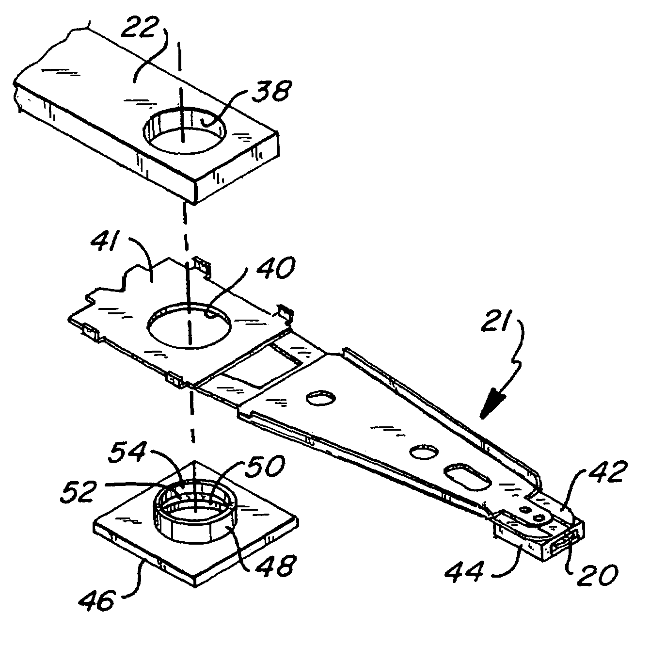
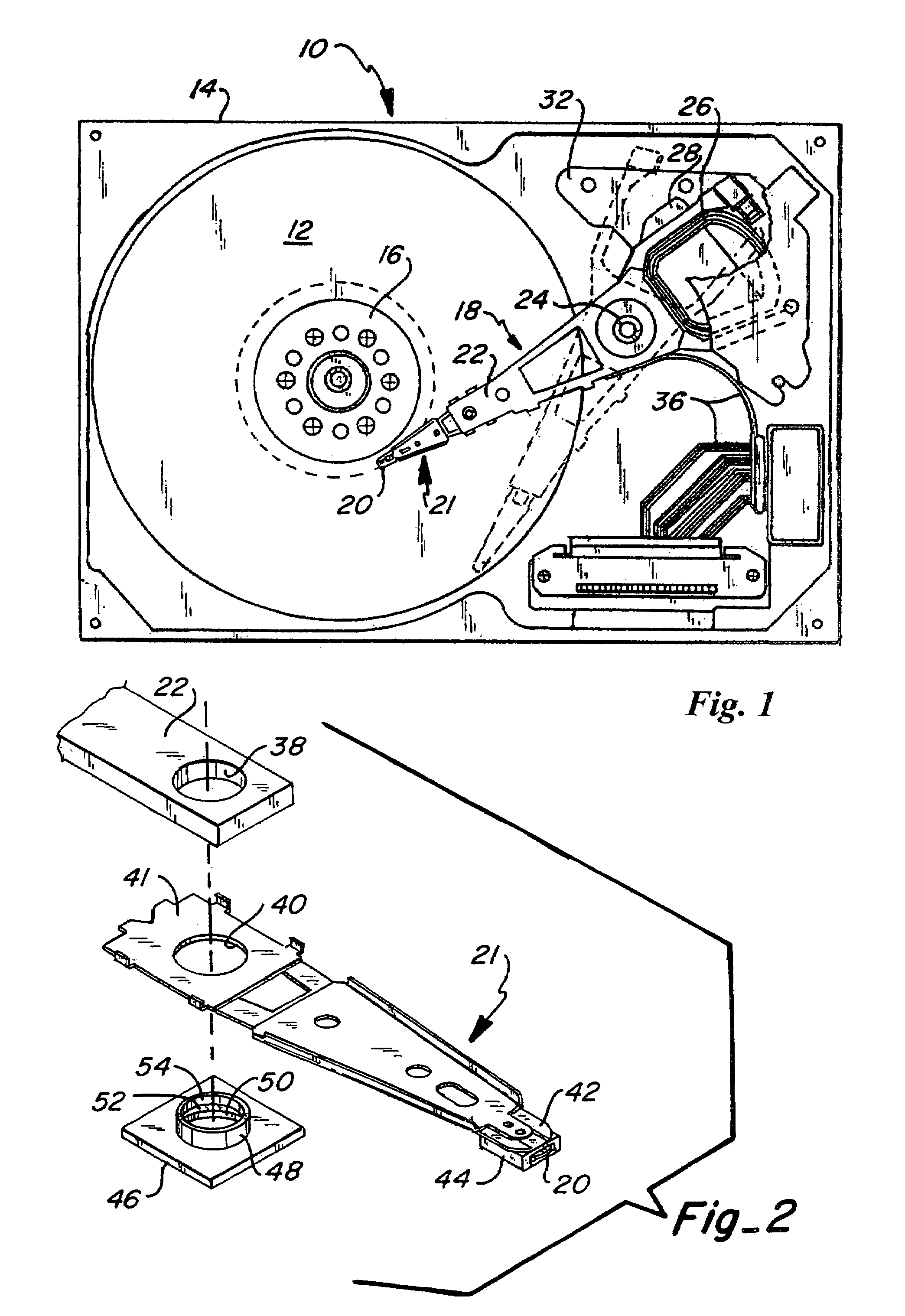
[0023]FIG. 1 shows a plan view of a disk drive assembly 10, with the top cover removed. FIG. 1 is representative of any number of common disk drives. The disk drive assembly 10 illustrated herein includes at least one disk 12, typically having magnetic media on both the upper and lower surfaces thereof. The disk 12 along with other components of the disk drive are contained within a housing 14. The disk 12 is mounted over a hub 16 which is driven by a motor (not shown) enabling the disk to rotate at high revolutions per minute during operation. An actuator assembly 18 is shown rotatably mounted to an actuator pivot 24. Basic components of the actuator assembly 18 shown include one or more read / write heads 20 mounted on a flexure arm or suspension arm assembly 21. Suspension arm 21, in turn, is attached to an actuator arm 22, as further discussed below. In solid lines, the actuator assembly 18 is shown parked over the landing zone. The landing zone has been represented by the area of...


PUM

PropertyMeasurementUnit
thicknessesaaaaaaaaaa
thicknessaaaaaaaaaa
thicknessaaaaaaaaaa

Abstract

A method is provided for assembling an actuator assembly of a disk drive. The method includes providing an actuator arm, providing a suspension arm, fixing a swage plate to the suspension arm, the swage plate including a swage boss extending therefrom, depositing a film lubricant upon at least an outer surface of the swage boss, and attaching the suspension arm to the actuator arm by swaging. A method is also provided for reducing torque out retention values between the actuator arm and the suspension arm when the actuator arm and suspension arm must be separated in a subsequent de-swaging process. This method includes providing an outer surface of the swage boss, and applying a lubricant film coating to the outer surface of the swage boss. A preferred thin film lubricant may be applied by emersion and draining, localized spraying, or various deposition processes. Application of the lubricant has also shown to improve gram load uniformity and to reduce adverse distortion to the actuator assembly which otherwise occurs during swaging.

Description

CROSS REFERENCE TO RELATED APPLICATIONS[0001]Priority is claimed from U.S. Provisional Patent Application No. 60 / 239,159, filed on Oct. 10, 2000, and entitled “Suspension Swage Plate Process” the disclosure of which is incorporated herein by reference in its entirety.FIELD OF THE INVENTION[0002]This invention relates in general to disk drives, and more particularly, to application of a solid film lubricant to components in a disk drive assembled by a swage process.BACKGROUND OF THE INVENTION[0003]Magnetic-disk drives generally utilize rotary actuators to position one or more magnetic read / write heads (also known as transducers) with respect to a similar number of magnetic disks rotatably mounted on a hub driven by a motor. The read / write heads are moved among particular tracks of the magnetic disk to gain access to the information recorded on that track and / or to write information to a particular location on the disk.[0004]The read / write heads are mounted on an air bearing slider. T...

Claims


Application Information

Patent Timeline
Patent Type & Authority Patents(United States)
IPC IPC(8): G11B5/127H04R31/00
CPCG11B5/4813Y10T29/49025Y10T29/49027Y10T29/4903Y10T29/49032Y10T29/53665
Inventor CROWDER, MARK S.RUPP, JR., RICHARD E.MCCRANDALL, JOHN
Owner MAXTOR
Why Eureka
Try Eureka