Independent timing retard for engine speed limiting

a technology of engine speed limit and timing retard, which is applied in the direction of speed sensing governors, machines/engines, ignition safety means, etc., can solve the problems of engine overspeed, sudden removal of workload, and difficulty in controlling, so as to reduce undesirable spikes in the maximum combustion chamber pressure

Active Publication Date: 2006-05-09
WALBRO LLC
View PDF13 Cites 15 Cited by
  • Summary
  • Abstract
  • Description
  • Claims
  • Application Information

AI Technical Summary

Benefits of technology

[0009]An exemplary method and system for operating an engine is provided, wherein engine ignition is activated according to a predetermined timing schedule that references engine speed. Engine ignition is suppressed above a predetermined engine speed threshold so that engine speed falls below the predetermined engine speed threshold, and thereafter engine ignition is reactivated according to timing that is retarded relative to the predetermined timing schedule for a predetermined number of engine revolutions, thereby mitigating undesirable spikes in the maximum combustion chamber pressure.

Problems solved by technology

Engine overspeed occurs when the engine is operating at high speed, such as wide-open-throttle, and some workload is suddenly removed from the engine, such as when a blade of an engine-powered chainsaw finally breaks through a log it is cutting.
Unfortunately, however, this method can be difficult to control and yields increased unburned fuel emissions that are exhausted out of the engine.
But this method typically occurs over an unacceptable number of engine cycles and yields engine inefficiency and high exhaust gas temperatures, which can harm various components of the engine.
Such combustion yields undesirable spikes in pressure in the combustion chamber that can be damaging to engine components and that otherwise create undesirable noise, vibration, excessive engine heating, high exhaust gas temperatures, and harshness in engine operation.
In sum, current approaches at engine speed limiting and recovery are not yet fully optimized for fuel efficiency, engine integrity, and smooth engine operation.

Method used


Image

  • Independent timing retard for engine speed limiting
  • Independent timing retard for engine speed limiting
  • Independent timing retard for engine speed limiting

Examples


Embodiment Construction

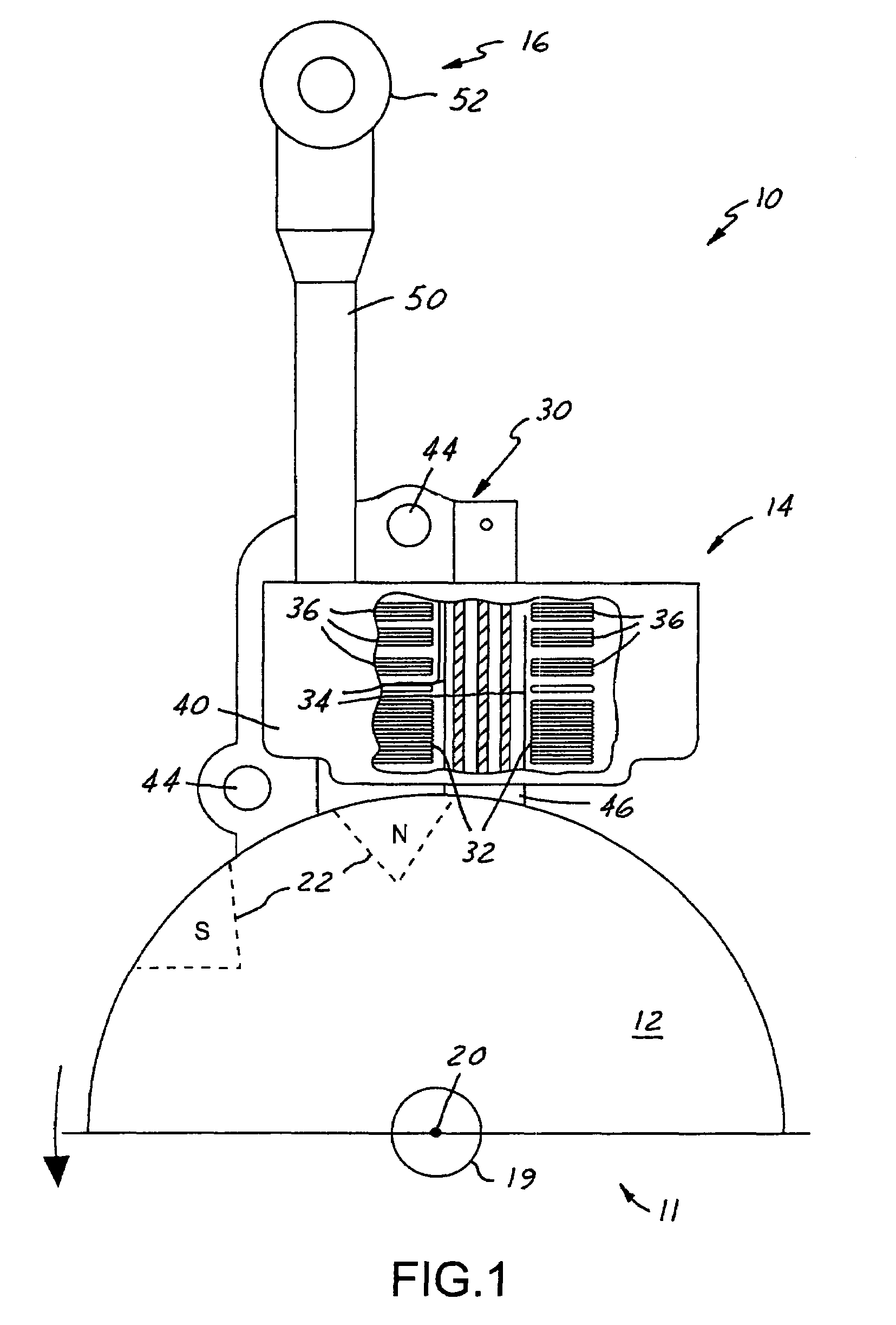
[0020]Referring in more detail to the drawings, FIG. 1 illustrates an exemplary signal generation or ignition system 10 for use with a low cost, light duty internal combustion engine 11, such as the type typically employed by hand-held and ground-supported lawn and garden equipment. Such equipment includes chainsaws, trimmers, lawn mowers, and the like. The ignition system 10 could be constructed according to one of numerous designs, including magneto or capacitive discharge designs, such that it interacts with an engine flywheel 12 and generally includes a control system 14, and an ignition boot 16 for connection to a spark plug (not shown).

[0021]The flywheel 12 is a weighted disk-like component that is coupled to an engine crankshaft 19 and thus rotates about an axis 20 under the power of the engine 11. By using its rotational inertia, the flywheel 12 moderates fluctuations in engine speed, thereby providing a more constant and even output. The flywheel 12 includes magnets or magn...


PUM


Abstract

A method and system for operating an engine wherein ignition of the engine is activated according to a predetermined timing schedule that references engine speed, and the ignition is suppressed above a predetermined engine speed threshold to allow engine speed to fall below the predetermined engine speed threshold. Thereafter, ignition is reactivated according to timing that is retarded relative to the predetermined timing schedule for a predetermined number of engine revolutions substantially when the engine speed has fallen below the predetermined engine speed threshold, thereby mitigating undesirable spikes in combustion chamber maximum pressure.

Description

FIELD OF THE INVENTION[0001]This invention relates generally to methods and systems for operating internal combustion engines and more particularly to methods and systems for regulating engine speed by suppressing engine ignition and controlling engine ignition timing.BACKGROUND OF THE INVENTION[0002]Many internal combustion engines use various methods and systems for regulating engine speed so as to avoid engine overspeed conditions. Engine overspeed occurs when the engine is operating at high speed, such as wide-open-throttle, and some workload is suddenly removed from the engine, such as when a blade of an engine-powered chainsaw finally breaks through a log it is cutting. Among the options for regulating engine speed, some engine designs incorporate fuel flooding, ignition timing retard, or ignition suppression.[0003]With any of these options, a spark-ignition engine cycle includes a compression stroke wherein a piston compresses an air-fuel mixture within an engine combustion c...

Claims


Application Information

Patent Timeline
Patent Type & Authority Patents(United States)
IPC IPC(8): F02P9/00
CPCF02P9/005F02D2400/06F02P1/086F02P11/025F02P3/083
Inventor ANDERSSON, MARTIN N.PATTULLO, GEORGE M.
Owner WALBRO LLC
Why Eureka
Try Eureka