Apparatus and method for generating and using multi-direction DC and AC electrical currents

a technology of electrical current generation and apparatus, applied in the direction of electrical launchers, diaphragms, surgical instruments for heating, etc., can solve the problems of inability to change the current direction of previously proposed systems, and inability to provide hydrogen fuel cells. to provide a practical hydrogen source for mass distribution

Inactive Publication Date: 2006-05-09
SULLIVAN JOHN TIMOTHY
View PDF31 Cites 17 Cited by
  • Summary
  • Abstract
  • Description
  • Claims
  • Application Information

AI Technical Summary

Benefits of technology

[0044]The new types of currents and corresponding voltages can be used to power a new generation of batteries, capacitors, motors, light bulbs, and plasma generators, as well as for hydrogen and oxygen generation, and further may be applied to applications ranging from electroplating of metals and plastics to transportation, to name just a few of the potential applications. In the field of medicine, the currents can be used in x-ray machines, to destroy cancer cells by placing a patient inside a coil to which the currents are supplied at frequencies known to kill cancer cells without affecting non-cancerous tissue, and in other

Problems solved by technology

However, none of the previously proposed systems involves changing the direction of current in a single one, or both, of the electrodes so as to vary the direction of current flowing between the electrodes by other than 180°.
Hydrogen fuel cells, in particular, have the potential to provide a completely non-polluting power source of electricity, not only for vehicles but also for electricity generation in general, but have been limited by lack of a safe distribution system for the hydrogen, and by the costs of generating the hydrogen in the first place.
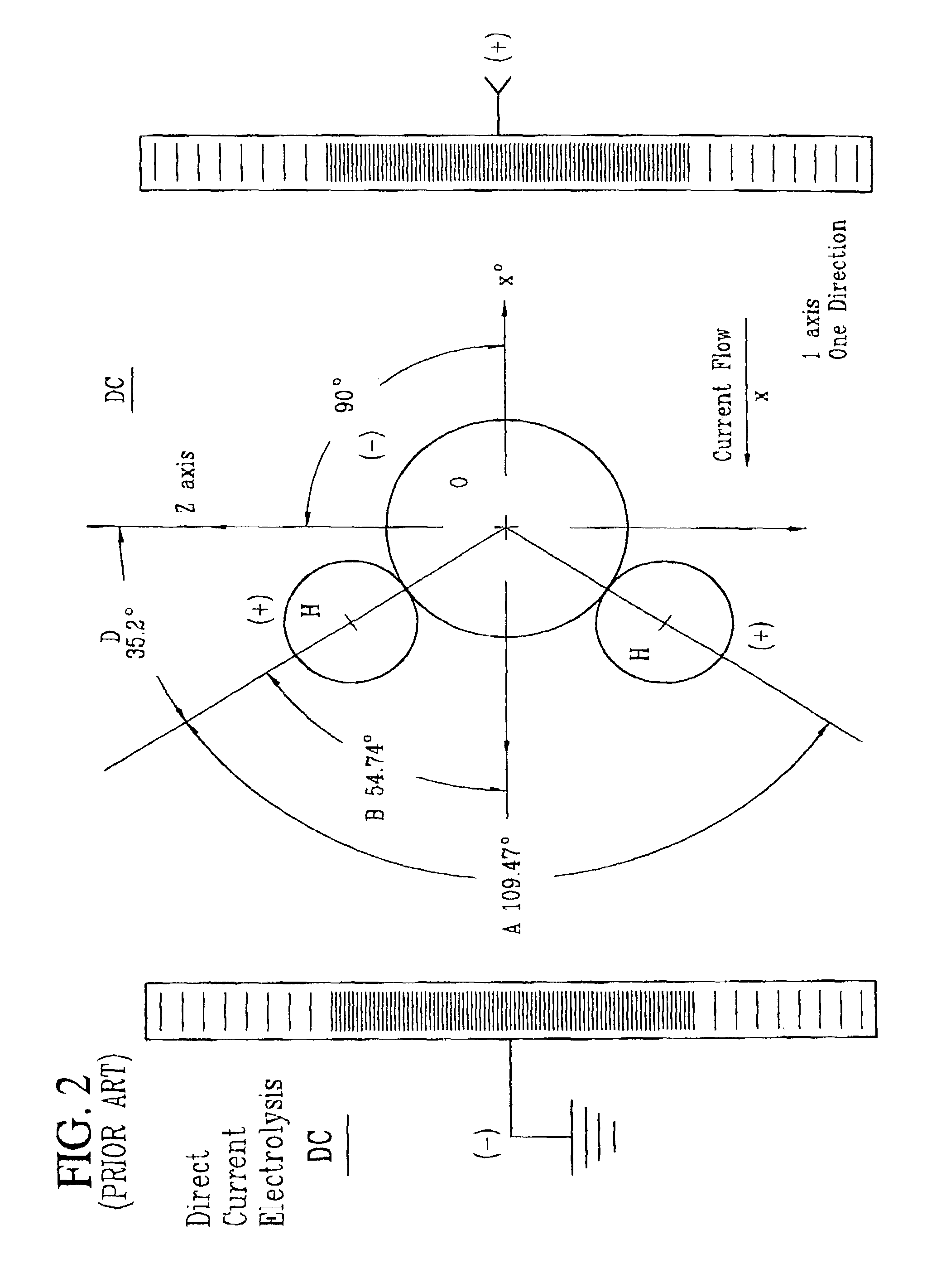
While it has long been known that hydrogen may be generated by applying a direct current to water, the rate of hydrogen generation is too low to provide a practical hydrogen source for mass distribution.
A

Method used


Image

  • Apparatus and method for generating and using multi-direction DC and AC electrical currents
  • Apparatus and method for generating and using multi-direction DC and AC electrical currents
  • Apparatus and method for generating and using multi-direction DC and AC electrical currents

Examples


Embodiment Construction

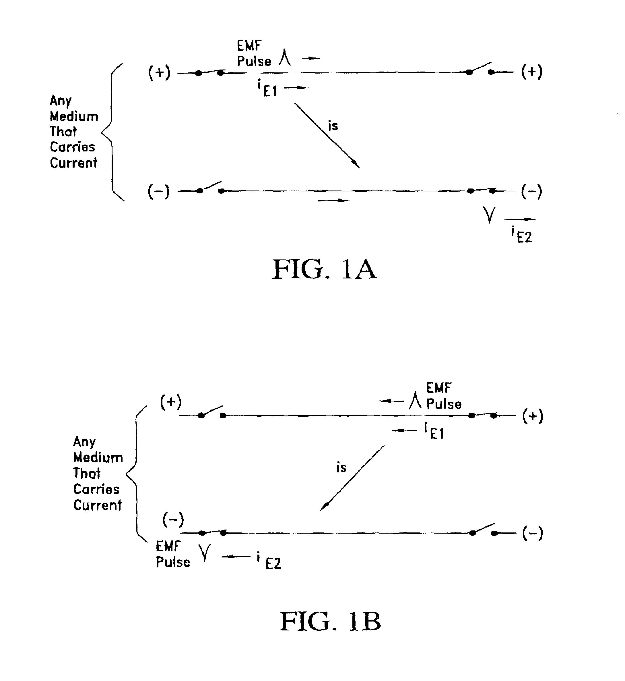
[0073]FIG. 4 illustrates an apparatus 1 which utilizes the principles of the invention to generate hydrogen and oxygen according to a first preferred embodiment of the invention. The apparatus 1 includes a tank 2, water supply 3, two electrical conductors 4,5 which form electrodes corresponding to electrodes E1 and E2 of FIGS. 1A and 1B for an electrolysis process, two conventional DC current sources 6,7, and four switches SW1–SW4.

[0074]The water 8 in this example may include a catalyst such as KOH, as is conventional, although the increased efficiency of the electrolysis process of the invention makes it possible to use ordinary tap water or water from rivers and lakes without adding additional catalysts.

[0075]When switches SW1 and SW4 are closed and switches SW2 and SW3 are open, current flows from the positive electrode of power source 6 through switch SW1 to conductor 4, and then is carried by ions in the water 8 to conductor 5, switch SW4, and the negative electrode of power so...


PUM

PropertyMeasurementUnit
Polarityaaaaaaaaaa
Magnetic fieldaaaaaaaaaa
Currentaaaaaaaaaa

Abstract

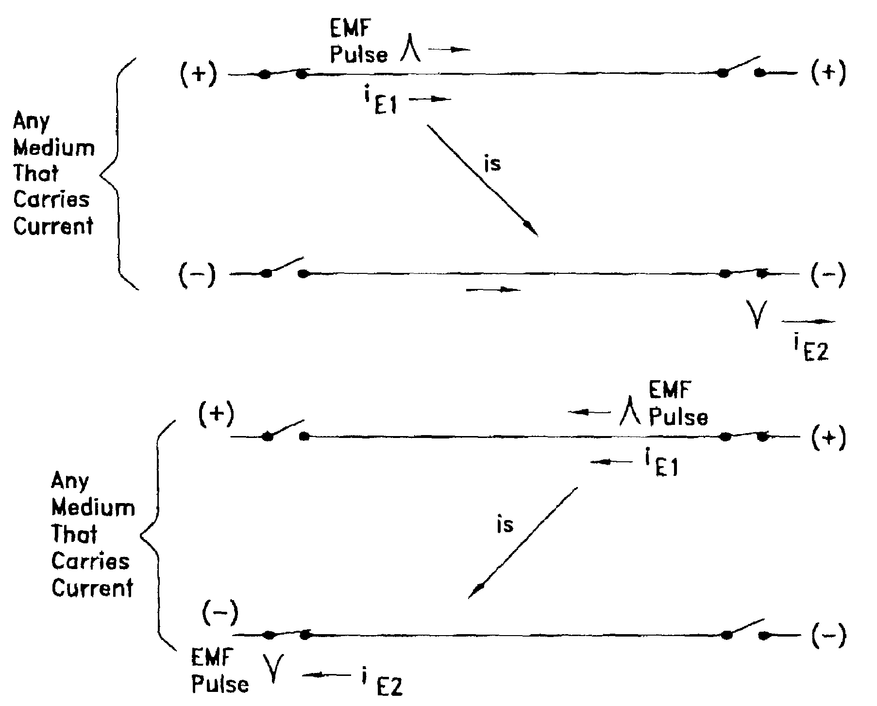
Multi-directional currents are generated in a medium by cyclically reversing the direction of a conventional current applied to at least one of at least two electrodes so that an electromotive force (EMF) pulse travels from side of the electrode to the other, changing the direction of current in the medium. The multi-directional currents may be used to accelerate electrolytic processes such as generation of hydrogen by water electrolysis, to sterilize water for drinking, to supply charging current to a battery or capacitor, including a capacitive thrust module, in a way that extends the life and/or improves the performance of the battery or capacitor, to increase the range of an electromagnetic projectile launcher, and to increase the light output of a cold cathode light tube, to name just a few of the potential applications for the multi-directional currents.

Description

BACKGROUND OF THE INVENTION[0001]1. Field of the Invention[0002]This invention relates to multi-directional, reciprocating electrical currents. The invention also relates to an apparatus and method for generating the multi-directional currents, and to applications of the generating apparatus and method.[0003]The multi-directional currents of the invention are generated in a current carrying medium by cyclically reversing the direction of a conventional current applied to at least one of a plurality of electrodes, so that an electromotive force (EMF) pulse travels from one side of the at least one electrode to the other, changing the direction of current flowing through the medium between two or more electrodes.[0004]The multi-directional electric currents have the effect of accelerating processes that rely on interaction between a current and the medium that carries the current, and of eliminating asymmetries that can lead to scaling or premature wear in batteries and other electrol...

Claims


Application Information

Patent Timeline
IPC IPC(8): C25B11/02C25B13/02C25B9/04F41B6/00C25B1/04H02J7/00H05H1/48A61B18/12C02F1/48C25B15/00H01M10/34H01M10/44
CPCC02F1/48C25B15/00H01M10/345H01M10/44A61B18/12C02F2201/483Y02E60/124C02F2303/04Y02E60/10
Inventor SULLIVAN, JOHN TIMOTHY
Owner SULLIVAN JOHN TIMOTHY
Why Eureka
Try Eureka