

Enhanced selectivity of zeolites by controlled carbon deposition
a technology of carbon deposition and selective zeolites, which is applied in the direction of catalyst activation/preparation, physical/chemical process catalysts, other chemical processes, etc., can solve the problems of high energy consumption and pollution generation of cryogenic distillation, non-regenerative process, and insufficient size exclusion alon
- Summary
- Abstract
- Description
- Claims
- Application Information
AI Technical Summary
Problems solved by technology
Method used
Image

Examples
example 1
Regeneration of Zeolite-L
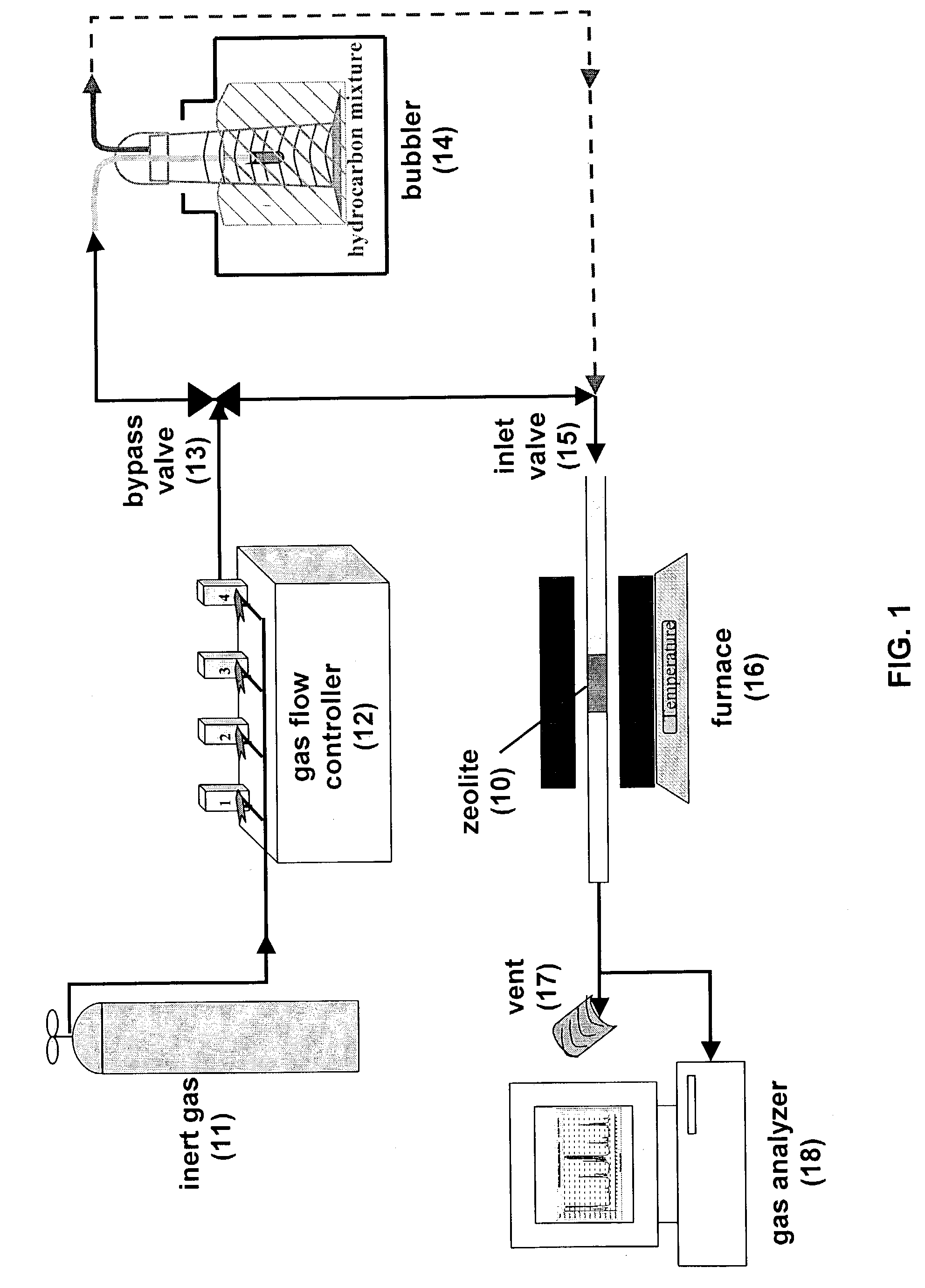
[0027]A bulk sample of zeolite-L was regenerated using the apparatus shown in FIG. 1. Either a stainless steel or a quartz tube was used in the tube furnace. The ⅜″ OD stainless steel tube or 10 cm OD quartz tube was washed with water and acetone and the tube was dried in a furnace at 1000° C. for about 2–3 hrs. One end of the tube was then packed with quartz wool. The tube was filled with approximately 1 g. of zeolite-L. The other end of the tube was buffered with quartz wool and the tube was shaken to avoid plugging. Both ends of the tube were tightened with swage locks. One end of the tube was connected to helium gas flow and the other end of the tube was left unlocked. A digital gas flow regulator was used to adjust the helium flow rate into the tube. The unlocked end was directed to the vent. A thermocouple was inserted through the unlocked end of the tube. The effluent from the downstream end of the tube was sampled by a mass spectrometer and then vent...
example 2
Carbonization of Zeolite-L
[0031]The regenerated zeolite-L was carbonized using the same apparatus shown in FIG. 1. While the furnace containing the regenerated zeolite-L described above was at 700° C., the helium flow was directed through a bubbler. The bubbler, containing a 80 / 20 (vol / vol) n-pentane / isoprene, was chilled at 0° C. The n-pentane / isoprene mixture was prepared by measuring the corresponding volume ratio of each hydrocarbon and putting the hydrocarbons into the glass cylindrical 250 ml bubbler. The bubbler was capped by parafilm. The top ends of the bubbler were swage locked and the bubbler was allowed to cool for about 20 min. In FIG. 1, the bypass valve was in the open position and the inlet valve was directed to the tube furnace. This allowed the helium carrier gas to flow into the bubbler and thereby carry the n-pentane / isoprene mixture to the furnace. The hydrocarbon-containing helium gas was flowed over the zeolite-L for 1 to 4 hrs. A P vs. T plot was monitored wi...
example 3
Separation of an n-Pentane / Isoprene Mixture with Carbonized Zeolite-L
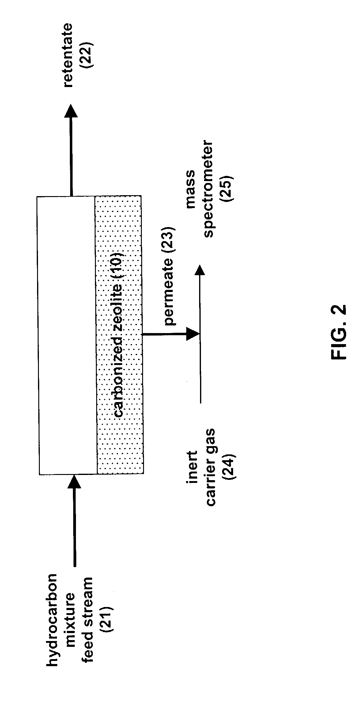
[0034]A light hydrocarbon mixture can be separated using the carbonized zeolite in the apparatus shown in FIG. 2. A column was packed with the carbonized zeolite-L prepared according to the carbonization procedure described above. A 80 / 20 n-pentane / isoprene mixture was chilled to 0° C. and flowed across the feed end of the column. Pure helium was flowed across the permeate end of the column and the permeate stream was analyzed by a mass spectrometer.
[0035]In FIG. 5 is shown the ratio of the linear hydrocarbon (i.e., n-pentane) to the branched hydrocarbon (i.e., isoprene) in the permeate stream. The permeate stream was enriched to over 6:1 n-pentane / isoprene by passing the hydrocarbon mixture through the carbonized zeolite-L column. After about 20 minutes, the carbonized zeolite-L became saturated with isoprene and the concentration of the permeate stream returned to 3.05:1 n-pentane / isoprene, the ratio resulting fr...
PUM
| Property | Measurement | Unit |
|---|---|---|
| Temperature | aaaaa | aaaaa |
| Fraction | aaaaa | aaaaa |
| Temperature | aaaaa | aaaaa |
Abstract
Description
Claims
Application Information